March 20, 2014

Assembly instruction for the Wireless Multi-sensor KIT

If you have decided to buy the KIT, you will have some SMD soldering in front of you.
It is not very hard to solder, but if you have a steady hand, a magnifier glass and strong light, it is of great help.

This is the first project for me where I use SMD-components, and with the size of the SMD components that I use, it is actually as fast or faster to solder compared to the old fashion through hole soldering.

Here is an excellent SMD soldering tutorial from the user lizerdboy79 at Youtube, https://www.youtube.com/watch?v=PxeWVCS15RU

When you receive your kit you first need to make sure all components are there.
Things you will need is,
  • Soldering station
  • Solder tin
  • Flux
  • Side cutter

Good to have,
  • Tweezers (to place components)
  • Magnifier
  • Strong light

You start to solder the components that build the lowest height from the PCB. That is the resistors, capacitor and LED. The orientation of the resistors and capacitor is not important. The resistors however must have the black side up.
The LED must be soldered with the right orientation. The bottom side of the LED has an arrow. This arrow should point to the (-)-marking on the PCB where the LED should be soldered.
Bottom side of the SMD LED

Marking on the PCB is the Cathode. The LED also has a green spot on the top that marks the location of the Cathode.


Start with cleaning the soldering pads on the PCB where the components will go. Then put some solder on one of the soldering pads for each component.
Take one component with the Tweezers and place it on the PCB. Pre-heat the pad where you put the soldering tin, and push in the component into the melted tin. Be quick. Remove the soldering tip. Let cool, and release the tweezers.
Once this is done, you can go ahead and solder the other side of the component.

Repeat for the rest of the SMD resistors, capacitor and LED component.

R1 - 1k
R2, R3 - 4k7
R4 - 4k7 (This resistor is optional. In the kit I have provided a 3-pin-header and a jumper instead)

Next is the mini USB type B connector (If you will use it).
The red arrows marks the power-pins. The yellow marks the data-pins.
You must solder the power-pins. Some USB power supplies automatically shut down if they do not sense any load between the data-pins (D+ and D-). This can be overcome by putting a solder blob between pin 2 and 3.

Add some flux to all the soldering pads.
Put some solder on one of the chassi pads.
Press the connector in place and apply heat to the soldering pad where you added the tin.
You should notice that the component sinks into place.
Solder the rest of the 3 chassi pads.
Last you solder pin 1 and pin 5 of the usb connector. They represent Vcc and GND.
If you want you can put a tin blob shortening pin 2 and 3. This will make sure that you can use any USB-charger to power the Wireless Multi-sensor.


Next up is the DIP 8 IC socket for the PIC12F675 microcontroller.


The orientation of the socket is not as important as the PIC12F675 orientation. However, there is a marking in the PCB that corresponds to the marking in the DIP-socket. Orient it accordingly. The red ring marks where pin 1 on the PIC12F675 goes.

Add some flux.
Place the DIP-socket in place and turn the PCB upside down.
Solder two of the pins in opposite corners. Pin 1 and 5 for instance.
Pick up the PCB and apply pressure on the DIP-socket and heat the pins where you soldered one at the time.
You should feel the socket sinks into place.
Solder the rest of the pins.

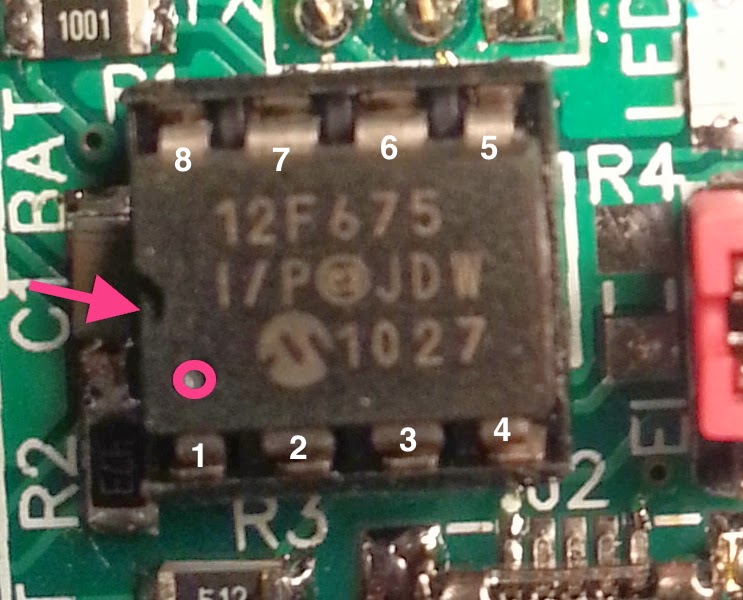
Place the PIC12F675 into the DIP-socket oriented as in the picture below.


The last thing to solder is the 3-pin header in the EI position (EI = Event Input).
Put the pin header in place and turn the PCB on the back and solder one pin.
At this point the pin header is probably not very straight positioned. Pick the PCB up and put one of your fingers on top of the pin header while you heat the pin you just soldered.
Make the pin header straight and let cool. Lay the PCB down again on the back, and solder the remaining pins. Once you have soldered all pins you can install the mini jumper, shortening the two pins closest to the LED. This makes sure that the Input pin is pulled to ground when it is not in use. If you forget this jumper and leave the pin header open, you will get sporadic PIR-events.

Continue read about how you mount the additional sensors in another blogpost.

March 19, 2014

Connection guide for the Wireless Multi-sensor

Here are the different connections to the Wireless Multi-sensor version 1.1.

First I start with presenting the different ways to connect sensors,

  • Temperature and Temperature/Humidity sensors
  • PIR and COsensors
  • Passive switch-type of sensors

In the end I show how you can power the Multi-sensor and where you can feed it, under the section Power.


Temperature and Temperature/Humidity sensors

The 1-wire network is ideally a straight bus. But it could as well be pure star-shaped. This shape is however not recommended by Maxim. For more detailed information about the network topology I recommend reading Guidelines for Reliable Long Line 1-Wire Networks.
A network length of about 50 meters have been reported to work OK with the Multi-sensor, but do not see this as the maximum limit. Maximum network length is still to be found. Cable type is important if you plan to build a large network. Pair-twisted EKKX 2x2x0,5 is one of the recommended cables to successfully build a large working 1-wire network.

The following 1-wire sensors have been verified to work, DS18B20, DS18S20, DS18B22, DS1820 and MAX31820.

With the DS2423-firmware the Multi-sensor will support the DS2423-2-channel counter commonly used when logging energy consumption. however there is a simpler way.

The DHT22 can be connected with up to 100m cable according to the specification.


PIR or CO2 sensor

You can choose from many different types of sensors to connect to the PIR-input. Any of those types (or similar) can be connected right into the pin connector after removing the read jumper thing.


Passive switch-type of sensors

Any passive switch-type of sensor can be connected to the PIR-input. With this type of sensor you will need to add a Pull-down resistor to force the DATA-line low when the switch is open. The pull-down resistor should have a value of about 4k7 to 10kOhm, but it is not critical.
A transmission will only be done as soon as the DATA-line goes high.

Power

You can power the Multi-sensor in one of two ways. Either you use the USB-port, or you use the solder pads on the PCB marked BAT for battery, to power it with the power source of your choice.
The table below will guide you with what minimum and maximum voltages that are allowed.

The numbers within the parenthesis are the maximum ratings for each sensor. However, the PIC-microprocessor limits the maximum voltage to 5.5V. I have tested it successfully with 6.5V, but that is outside the PIC12F675 specification and not recommended.

You will be safe to feed the Multi-sensor with 4.5-5.5V independently of which sensors you combine. The easiest way is to use a USB-charger or similar. The USB port is only there to give power to the Multi-sensor. The D+ and D- pins are not used.

If you want to minimise the form factor you will likely want to choose a small battery. It can be useful to know that you can go as low as 3.0V as long as you only use 1-wire DS18X20 sensors. I have successfully powered a Multi-sensor and one DS18B20 with a CR2032 cell battery (3V). The test was speed up with increased transmission interval. The estimated lifetime of this configuration is estimated to more than 1.5 years.

The transmitting range of the Multi-sensor will depend on the voltage level.
Here is the specification for the Radio module used in the Multi-sensor (FS1000A):
Operating Voltage2.5 V to 12 V
Operating Current4mA @ 5V, 15mA @ 9V
Quiescent Current10uA
Operating Temperature-10C - 60C
ModulationASK
Max. Data Rate2.4K
Data InputTTL
RF Power20 mW@5V

For the advanced user it could probably be possible to boost the transmission range by feeding the RF module with 12V separate from the rest of the Multi-sensor.


March 9, 2014

Update: CO2 sensor support for the Wireless Multi-sensor

I am getting closer to a working version of the firmware that support the CO2-sensor S8 from SenseAir®.
You can get it from m.nu.

The sensor measures CO2 levels from 0 to 2000ppm and the Wireless Multi-sensor outputs this as 0.0°C - 100.0°C which corresponds to 0.0% - 100.0% of 2000ppm.

Here is a graph from the bedroom last night,
It averages around 50% during the night. This corresponds to around 1000ppm.
At first the sensor was placed outside, where the level is quite steady at 400ppm. The Wireless Multi-sensor outputs 20%.

We started the night with me and my two sons in the bedroom. The CO2 level increases until 3 o'clock, to a maximum of 56%. At 3 o'clock my eldest son leaves the bedroom and the CO2-level decreases to about 50%. After 6 o'clock me and my youngest son leaves the room and my wife enters and continue to sleep alone in the bedroom. The peak is probably me breathing too close to the sensor when checking its position.

The remaining task is to make this work together with DHT22 and the 1-wire-network. The Wireless multi-sensor is supposed to automatically detect if you have connected a CO2-sensor or if you have a PIR-sensor or other type of TTL logic type of sensor.

UPDATE: Here is another graph that shows the CO2-ppm level on the y-axis. The snapshot is taken after one night sleep with my wife and my eldest son in his bedroom.

Top notation is 1306ppm just before 7 o'clock in the morning.