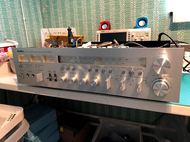
I decided to do a full recap (replace all electrolytic capacitors). Well most of them. I actually left the radio and phono pcb as it was.
There are three Service Bulletins released by Yamaha for the CR2020. They all target the same problem area. Heat problem in the power supply area. One of them also target a problem with power switch waring out.
The main capacitor board is the worst heat producer. The PCB in this amp had become so hot that the PCB had become charcoal and the electrical traces lifted from the PCB.
Most of the heat is produced by four current limiting resistors. The original ones are mounted on the component side and in a way that generate heat in a bad spot. I googled the problem and found out that someone else had solved the problem. Mounting the heat generating components on the back of the PCB make it much easier for the heat to move away from the PCB.
-B and +B terminals are marked on the PCB. This is where the cables to the main board is soldered. They connect immediately to the capacitors. As a side note, I experienced the importance of isolation distance. After a full day of testing the amp and adjusting bias, I turned it off. The day after when turning it on, I heard a loud bang! It turned out that the +B cable was lying right on to the negative terminal of the capacitor. When switching on the amp the current flow to the capacitors is very high and thus the voltage shortly spikes. The voltage became so high that there was a spark through the cable isolation. After relocating the cable the problem was solved.
After the recap and restore was done, there was quite a hand full of retired components. All of them is not shown in the picture.
The capacitors where in a really bad shape.
The orange capacitors to the left was the only capacitors that still measured very good. The rest was in bad shape with many only having half the capacitance left. The capacitors in the rest of the red circles had a short circuit.
Closing up on the relay one can see that the contact pads are missing on one side.
The under dimensioned transistors TR712 and TR715 (2SD234) was upgraded to TIP41C and mounted on a big metal surface close to the faceplate. In the image below one can also see the new relay and the new green capacitor board.
Here is a close-up on the capacitor board. The two big capacitors are new 5-pin snap-in type capacitors.
The Main boards had a couple of short circuit capacitors but nothing else broken. However, I did change the potentiometer to trim the bias voltage and refreshed the thermal paste on all transistors. At the same time I checked that they seemed OK. The transistor to the right TR608 was changed since the 2SC458 is known to go bad.Image below is before restoration.
Main boards after restoration.
The power switch came in a plastic bag. It consist of a mechanical part and an electrical switch part. The mechanical part was in perfect condition but not the electrical part. I 3D-printed a small bracket that made it possible to mount a micro-switch (CSM40550) to the mechanical switch.
And a final picture of the result.


