I wanted a sturdy but simple Sim Racing H-pattern shifter compatible with my Fanatec CSL Elite wheel. This is what I came up with.
 |
| 3D model. Front PCB has an RJ12 connector to connect to the wheel base. The long center nut is very long in the rendering. |
All DIY variants of sim shifters that I found seem not very sturdy and usually not very simple in the construction.
My shifter is simple in the mechanical construction, and it contains relatively few parts. The electronic circuit is simple, at least for most of the diy-people. And foremost, it is very sturdy.
The shifter uses hall effect switches and position sensors that will never wear out. I have simplified the electronics so that few components are needed.
There are not many tools needed either.
The surfaces that wear is in metal where needed. X- and Y-axis joints have small ball bearings that are press fitted to the plastic parts.
The shifter uses two spring loaded ball screws that give the shifter three distinct positions in the Y-direction. The X-direction is a smooth motion. X-position is centered by two, commonly used 3D-printer hotbed springs 8mm diameter and 20mm long.
There are only three 3D-printed parts. The 4th part is a drill jig for drilling the hole in the central extension nut. The 5th part is a drill jig for creating the mounting pattern for the shifter if needed.
 |
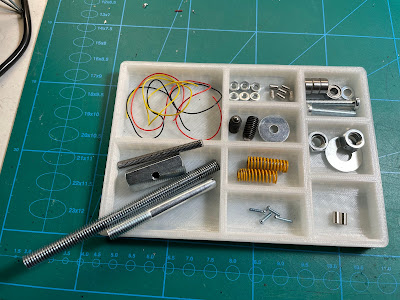
| Parts needed for assembling the shifter |
Prepare the metal parts
The center joint is made of a 30-35mm long M8 nut. There need to be a M5 threaded hole in the middle of the nut. 3D-print the jig to help creating a perfectly centered hole in the nut. Use a 4.2mm drill for best result with the threading tap.
Press the long nut into the jig and drill all the way through. Then make a M5 thread in the hole. Clean the threads afterwords, otherwise it is difficult to screw in the M5 rod at a later stage.
Cut off a 55mm long piece of the threaded M5 rod. Make a small slot in each end. Fasten one of the magnets in one of the ends of the rod. I used a small round file to make a rounded seating for the magnet. The slot on the other end is for being able to use a flat head screwdriver when mounting it to the long center nut.
Cut a 100mm long piece of the threaded M8 rod. This rod decides how long your shifter stick will be, and in turn also how long travel the shifting stick action will have.
Also cut the head off the75mm long machine bolt so that it ends up to be 68mm. The bolt to be used is preferably not threaded all the way. If this bolt is longer than 68mm it will protrude on the bottom of the shifter shell.
Prepare the X-block
Press in the 6 M4 nuts as far in as possible. Start with the top and bottom nuts and lastly the middle one. Repeat for the three nuts on the other side of the center axel. Screw in the 6 M4 grub screws so that they still have some threads that grip each of the nuts. The pits that form will give the distinct Y-positon of the shifter. If you like to have a less distinct positions you screw in the grub screws less deep. The grub screws also make sure the nuts stay firmly in place.
Press in all the 4 bearings in the X-block. There should be a tight fit on all the parts. Use a hammer to get them in place.
Use the angle ruler to scratch a 45° line in the X-block from top-left to bottom-right passing the bearing center. This will be used as a guide to position the magnet in a later step.
Screw the M8 threaded rod into the M8 long nut. Do not pass the center hole.
Place it down the X-block center and screw in the M5 threaded 55mm rod. The rod should be screwed in from the side where there are two small holes in the X-block. The M8 rod should also point out from the X-block side with rounded edges. Screw the M5 rod in until the top of the magnet is level with, or just under the X-block edge. Using a flat head screwdriver from the other side makes it easy to screw it in.
Calibration: With the M8 rod in the center position pointing upward: Orient the M5 screw so that the magnet SOUTH pole points between 10 and 11 o´clock when facing the magnet end of the M5 rod. Use a compass to know your pole, or hang it in a thin thread and see how it orients itself. The magnet should align with the earlier made line in the X-block.
Once the magnet orientation is done, secure its position by fastening the M8 rod firmly with some pliers.
Make sure that when moving the stick from max left to max right position, the magnet SOUTH pole should never pass 9 or 12 o´clock position.
Now screw in the 68mm cut M8 bolt from the other side of the long nut. First add some Loctite to keep it in place, and fasten it firmly with some pliers.
Tip the shifter over to one side and slide in one of the springs into the hole on the inside of the x-block. Repeat for the other side. The shifter stick should now be centered.
Press in the second magnet into the 4mm hole, flush with the X-block side.
 |
| This is how it should look when done. |
Screw in the two spring loaded M8 ball screws until they almost protrude on the other side.
Screw in the two M5 screws on both sides until they almost protrude on the other side.
Mount the three cables for the X-axis PCB. I used a dab of hot glue here and there. Make sure enough cable is exposed in both ends. The cable need to be flexible since one end connect to the moving X-block. Do not use single core cable.
Assemble the X- and Y-blocks
Place the M5 washer onto the M5 screw on the opposite side of the spring loaded ball screws. Put some grease on the 6 nuts and slide in the X-block with the 6 nuts facing the spring loaded ball screws into the Y-block.
Screw in both M5 screws all the way. Screw in one of the spring loaded ball screws while moving the X-block back and forth. Once the ball screw start to engage with the nuts, the Y-positions should become more and more distinct. Continue to screw in the second ball screw. If you like stiffer shifter you fasten the ball screws more. Note! Do not over tighten the ball screws.
Screw a nut onto the M8 threaded rod and add a washer. Screw on the shifter knob as far as it goes, and then unscrew the nut until the washer press onto the bottom of the knob and lock it in place.
PCBs and electrical connections
Mount the RJ12 PCB to the front of the Y-block.
Push in the hall sensor switches (AH3574) into the slots in the Y-block. Take note how the AH3574 are oriented to know which of the legs are GND, Output and VDD. Connect the top sensor to a4 (Y-out) and bottom one to a3 on the RJ12 PCB. Also connect GND and VDD. Hot glue any loose cable. Also hot glue the sensor switches in place so that they do not fall out from their slots.
Mount the X-axis PCB to the X-block using M2 screws. Solder the cables to the X-axis PCB and secure them with some hot glue in the PCB end as a stress relief. Make sure that there is some slack in the cable so that the X-block can move without straining the cables. Solder the other end of the cables to the RJ12 PCB.
Hot glue the cables soldered to the RJ12 PCB.
Plug in the H-shifter to your Sim wheel base and calibrate the wheel base so that it interpret the shifters output values as gears. How the calibration is done depends on your steering wheel. Look it up on youtube.
Enjoy!
Bill of materials
3D printed parts (https://www.thingiverse.com/thing:5025316)
- X-block
- Y-block
- Shifter knob
- Drill jig for the M8 long nut
- Drill jig shifter mounting pattern
Electronics
- 1x MCP6N11-010E/SN-ND MCP6N11-010E
- 1x 223-1562-1-ND G-MRCO-037
- 2x 31-AH3574-P-ACT-ND AH3574-P-A
- 1x 1727-1875-1-ND BC807-40 PNP
- 1x 380-SS-90000-007-ND RJ12 6p6c
- 1x 311-1.0KHRCT-ND 1k 0603 SMD
- 5x 311-4.7KHRCT-ND 4k7 0603 SMD
- 1x 311-47.0KHRCT-ND 47k 0603 SMD
- 1x 311-56.0KHRCT-ND 56k 0603 SMD
- 3x 1276-1006-1-ND 100nF Ceramic capacitor 0603 SMD
Hardware
- 1x Nut M8
- 1x Washer M5
- 1x Washer M8
- 2x Spring ball screw M8, https://www.amazon.se/gp/product/B08T8Z2VBR/ref=ppx_yo_dt_b_asin_title_o00_s01?ie=UTF8&psc=1
- 2x Spring 8mm x 20mm 3D printer hotbed style, https://www.amazon.se/gp/product/B07QTZXXHP/ref=ox_sc_act_title_4?smid=AS4K6ASZ3B0CX&psc=1
- 1x Nut 30-35mm long M8, https://www.biltema.se/bygg/fastelement/muttrar/forlangningsmuttrar-2-st-2000018782 Art.no. 19-516
- 1x Threaded rod 55mm M5, https://www.biltema.se/bygg/fastelement/specialskruvar/gangstang-blankforzinkad-2000017295 Art.no. 19-385
- 2x Bolt 35-40mm M5
- 4x Screw 2mm M2 (to fasten PCBs. Need to fit in 2.2mm PCB holes),
- 4x Ball Bearing 685ZZ 5x11x5mm, https://www.amazon.se/MR105ZZ-GROOVE-Kullager-flänsad-remskiva/dp/B098WWBVZX/ref=sr_1_2?dchild=1&keywords=685ZZ&qid=1634473423&sr=8-2&th=1
- 1x Threaded rod 95mm M8, https://www.biltema.se/bygg/fastelement/specialskruvar/gangstang-blankforzinkad-2000017295 Art.no. 19-387
- 1x Bolt 75mm M8 smooth, https://www.biltema.se/bygg/fastelement/bultar/vagnsbult-2000017862 Art.no. 19-064
- 2x Magnet 4x7mm cylindrical, https://www.amazon.se/gp/product/B00TACMN1I/ref=ppx_yo_dt_b_asin_title_o01_s00?ie=UTF8&psc=1
- 6x Nut M4 ISO4032 DIN934, https://www.biltema.se/bygg/fastelement/muttrar/mutter-2000046459 Art.no. 89-407
- 6x Grub screw 4-10mm M4, https://www.amazon.se/Gesh-stål-hexuttag-punkt-skruvar/dp/B08W4ZLLKS/ref=sr_1_3?dchild=1&keywords=grub+screw+m4&qid=1634473196&sr=8-3
- 1x Metal angle bracket, https://www.biltema.se/bygg/byggbeslag/vinkelbeslag/vinkelbeslag-2000017271 Art.no. 19-609
- 2x Metal tube clamps 21-23mm, https://www.biltema.se/bygg/vvs/rorinstallationer/rorklamrar/rorklammer-21---23-mm-2-pack-2000047110 Art.no. 86-9013
- 2x Machine screws M8 to mount the angle bracket to the tube clamps
Tools
- Drill for metal 4.2mm, https://www.amazon.se/gp/product/B00725AOIE/ref=ppx_yo_dt_b_asin_title_o00_s00?ie=UTF8&th=1
- Thread cutter tap M5, https://www.biltema.se/verktyg/handverktyg/gangverktyg/gangtapp-2000042861 Art.no. 18-353
- Hacksaw or Dremel to cut steel
- Loctite
- Ruler with 45° angle
- Hot glue gun
- Hammer, or similar
- Drilling machine
- Round file with 4mm diameter is nice to have to make a good seating for the X-axis magnet


