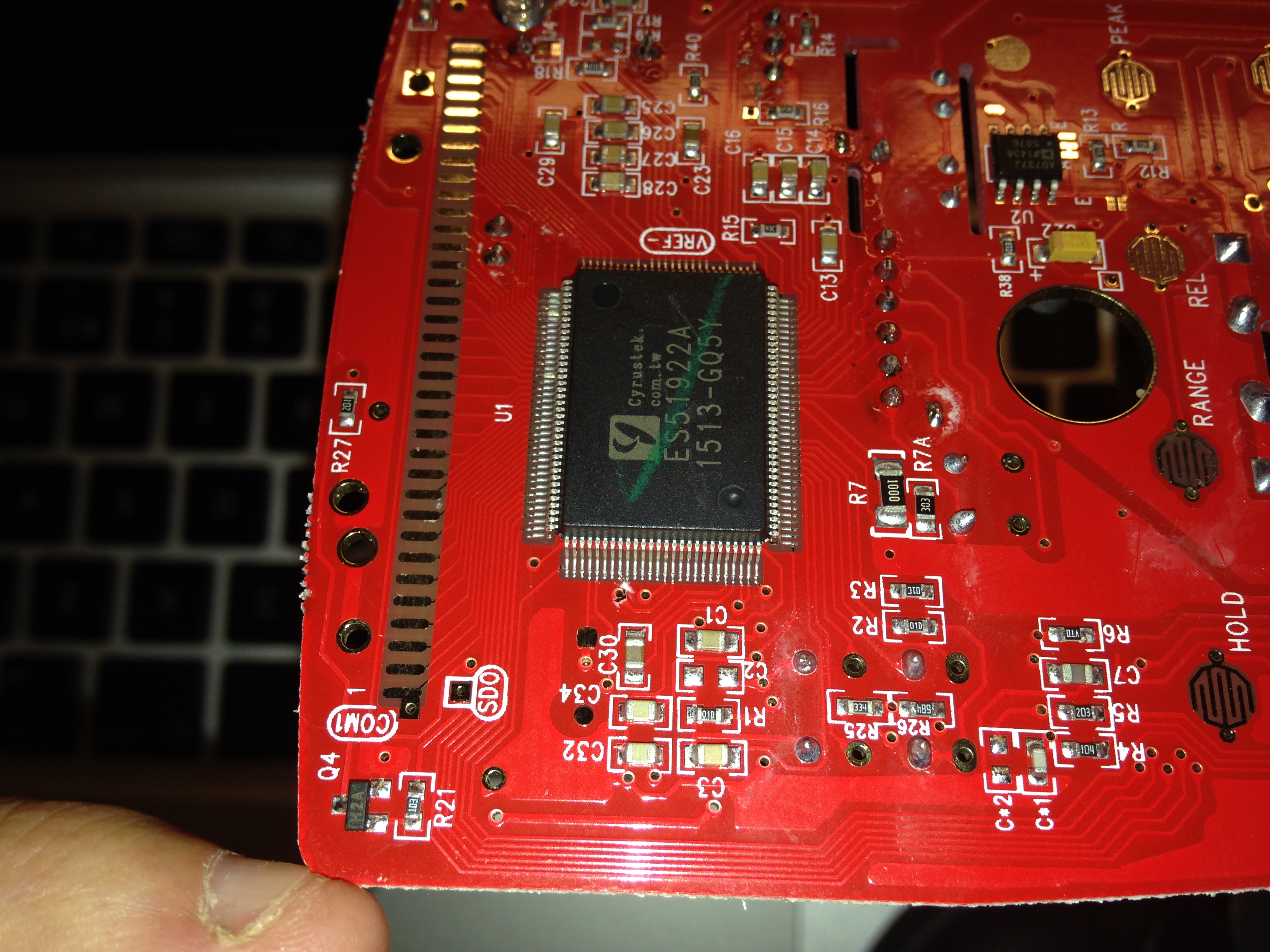
One of them is my multimeter UT61E from UNI-T that is a pretty good multimeter for the hobbyist.
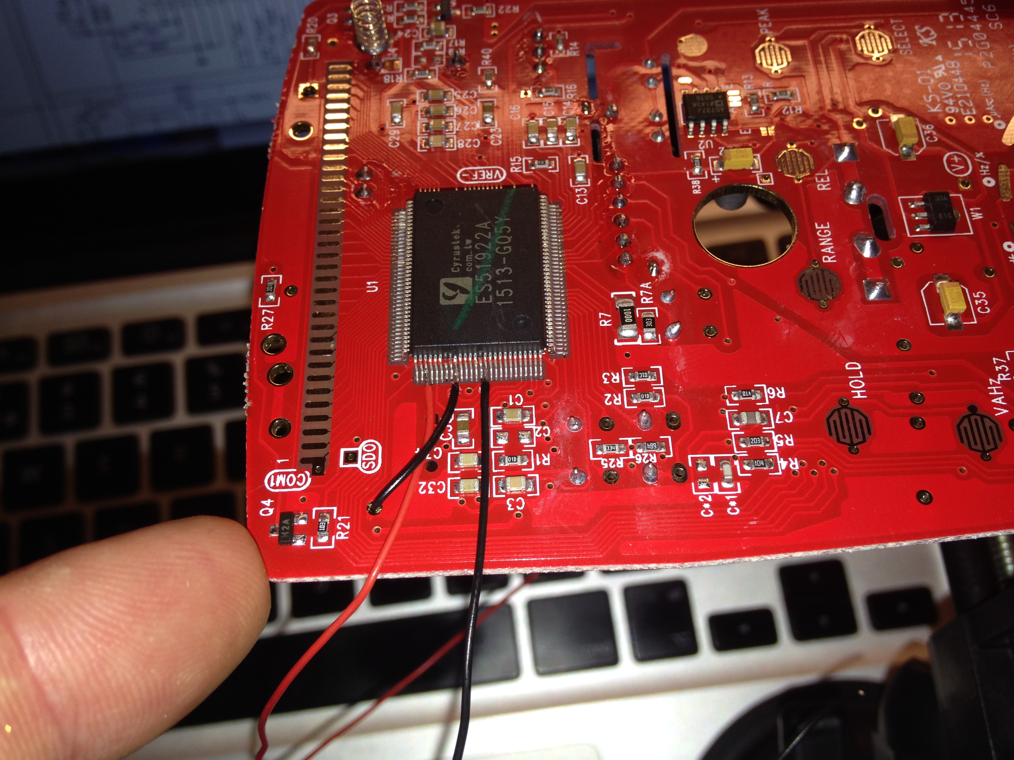
The onboard processing chip ES51922 have more features than is presented to the user. This hack enables some of them.
After the modification my multimeter have the following additional features;
- Backlit LCD with backlight auto shut-off
- DMM auto power-off after 15 minutes
- Possible to Enable/Disable RS232. Default is to have RS232 Disabled
- MAX-MIN mode for Frequency and Duty cycle measurements
- AC Low Pass Filter mode
There are some more tweaks to the tweak that can be done;
- Increase LCD backlight shut-off time from 60 to 180 seconds by connecting BKSEL (113) to VB_ (-3V). It is floating by default
- Increase the auto power-off time to 30 minutes by connecting APOSEL (112) to VB_. Default is floating.
I add more modes that is triggered by long-pressing each button or by pressing both buttons simultaneously or by holding down the yellow button while powering on.
This is not my own hack but rather a compilation of already existing hacks with some additions.
I have however not seen anyone done this with a PIC from Microchip. Nor using the PIC to drive the LEDs to protect the MM processing chip.
I have also enabled the LPF in AC-mode which I have not seen been done earlier.
Prerequisites
- 2 pcs LED. The forward current must not exceed 3V
- 1 pcs Resistor to limit the current to the LEDs. Its value depends on the LEDs forward voltage drop
- 2 pcs Resistor as a voltage divider for the BKOUT signal. Around 40k-60k should be OK.
- 1 pcs PIC16F688 microprocessor from Microchip
- 1 pcs 0.1uF capacitor for decoupling the PIC16F688
- Thin connection wire
- Hot glue and super glue is good to have
- PicKit2 or PicKit3 to program the PIC16F688 microprocessor
The modification
Download the source code from here,https://bitbucket.org/foogadgets/ut61e-modification
Build the hex-file.
Flash the PIC16F688 with the generated hex-file.
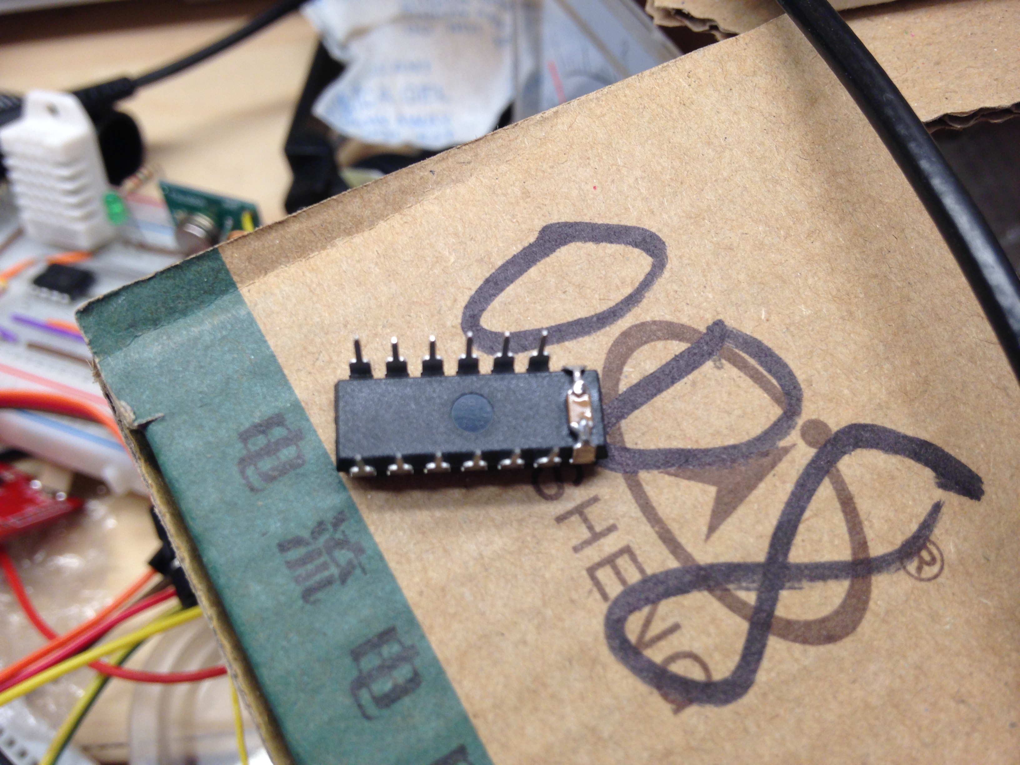
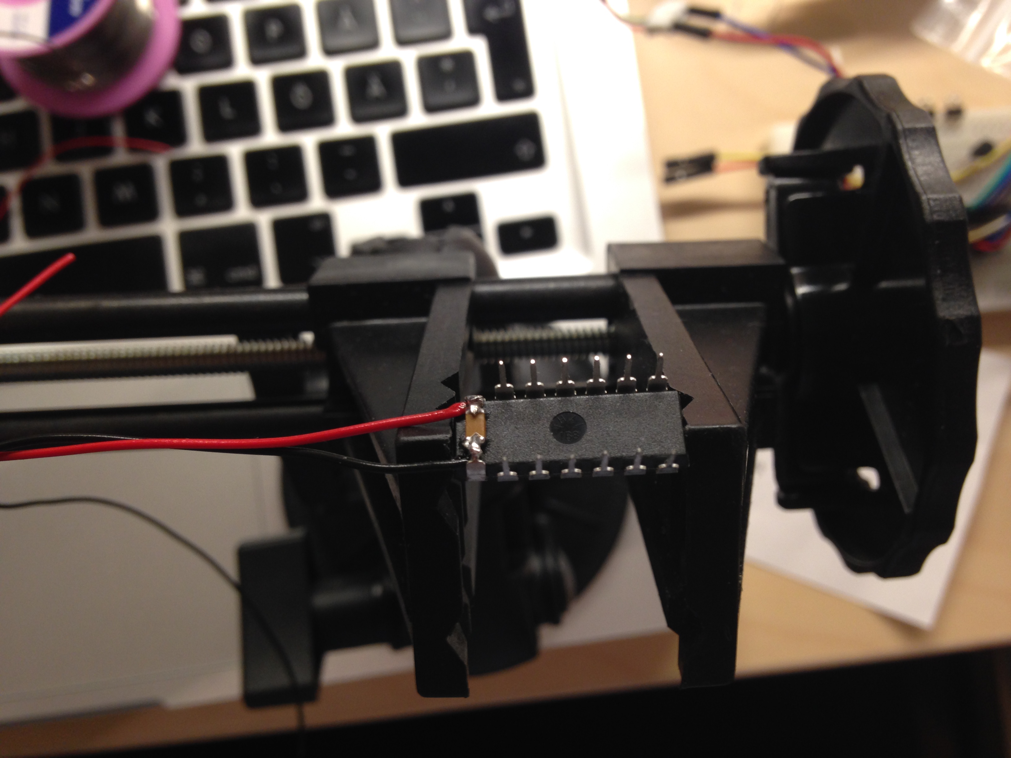
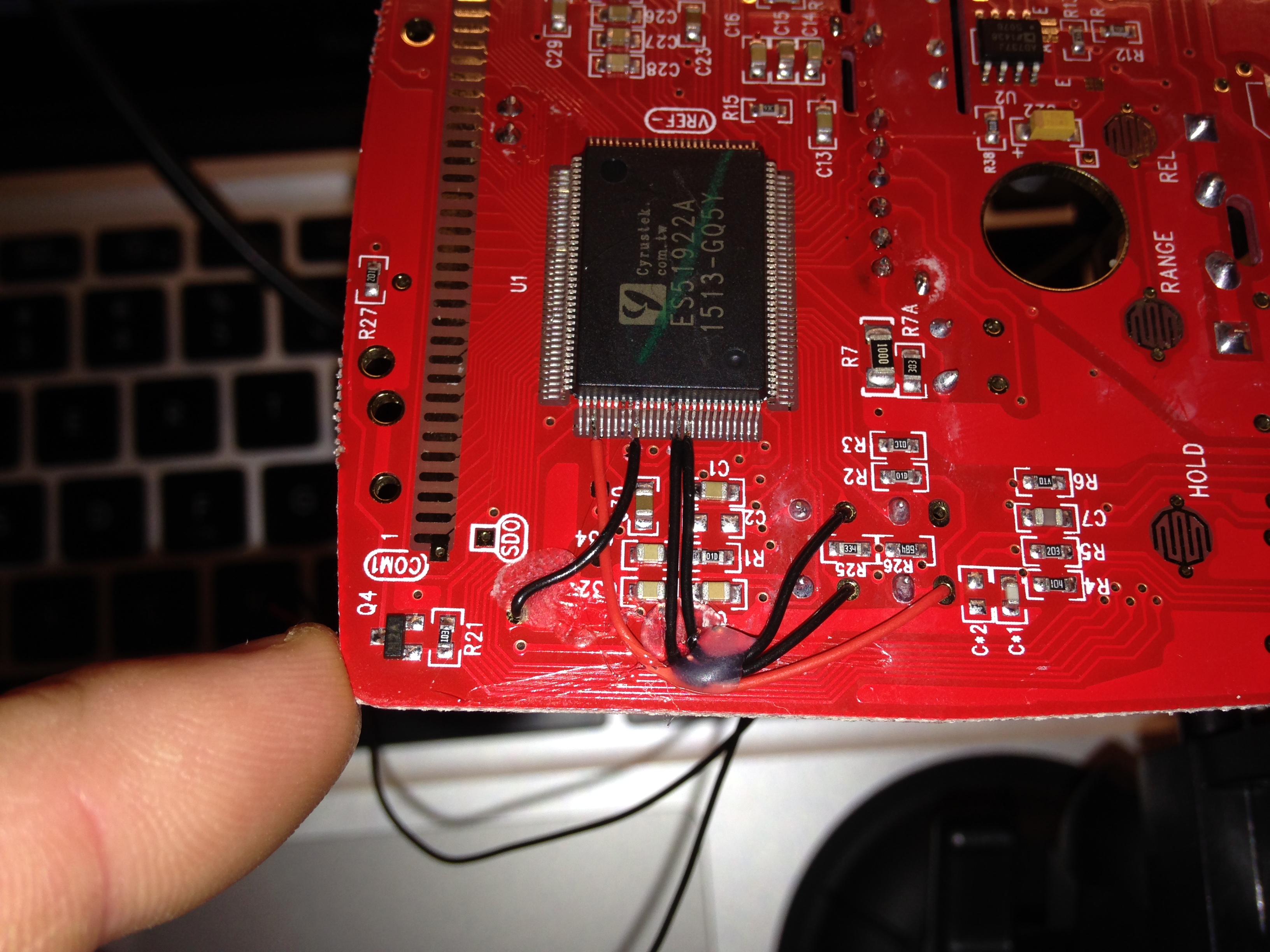
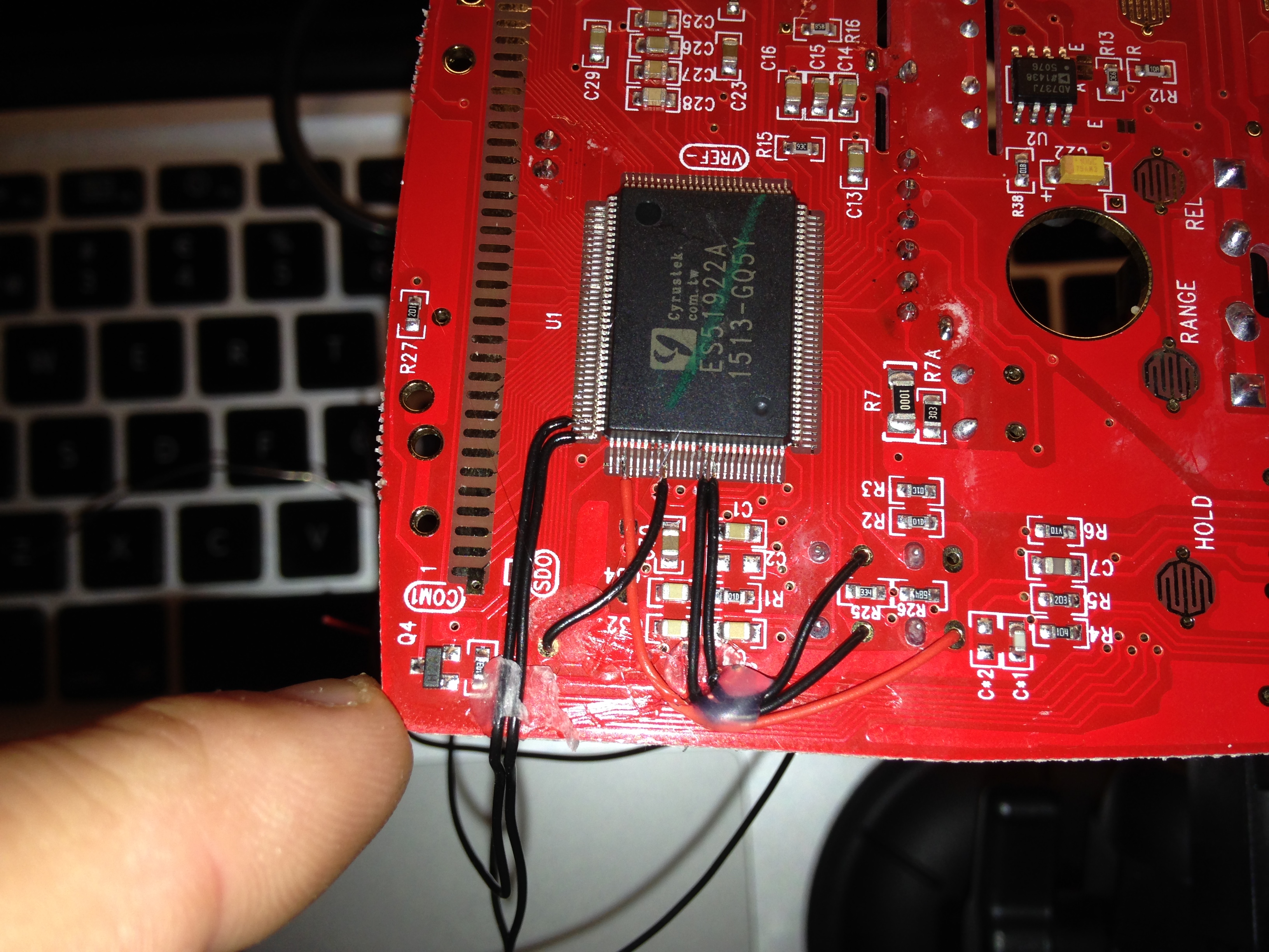
Solder the decoupling capacitor between pin (1) and (14) on the PIC.
Solder thin cables on all pins except pin (4).

Here is a video of the final result,
https://www.youtube.com/watch?v=KLrDdRcWR2Y
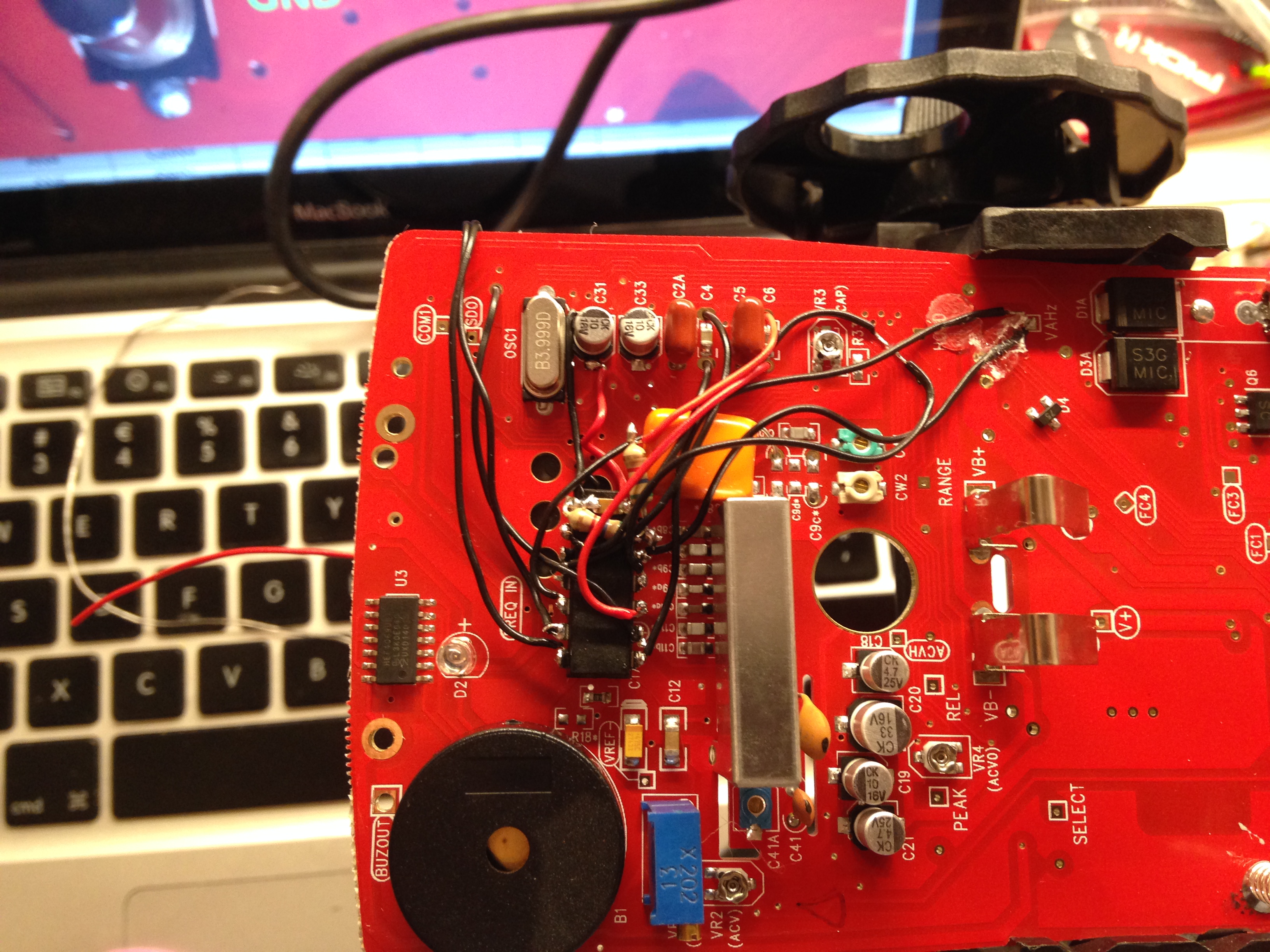
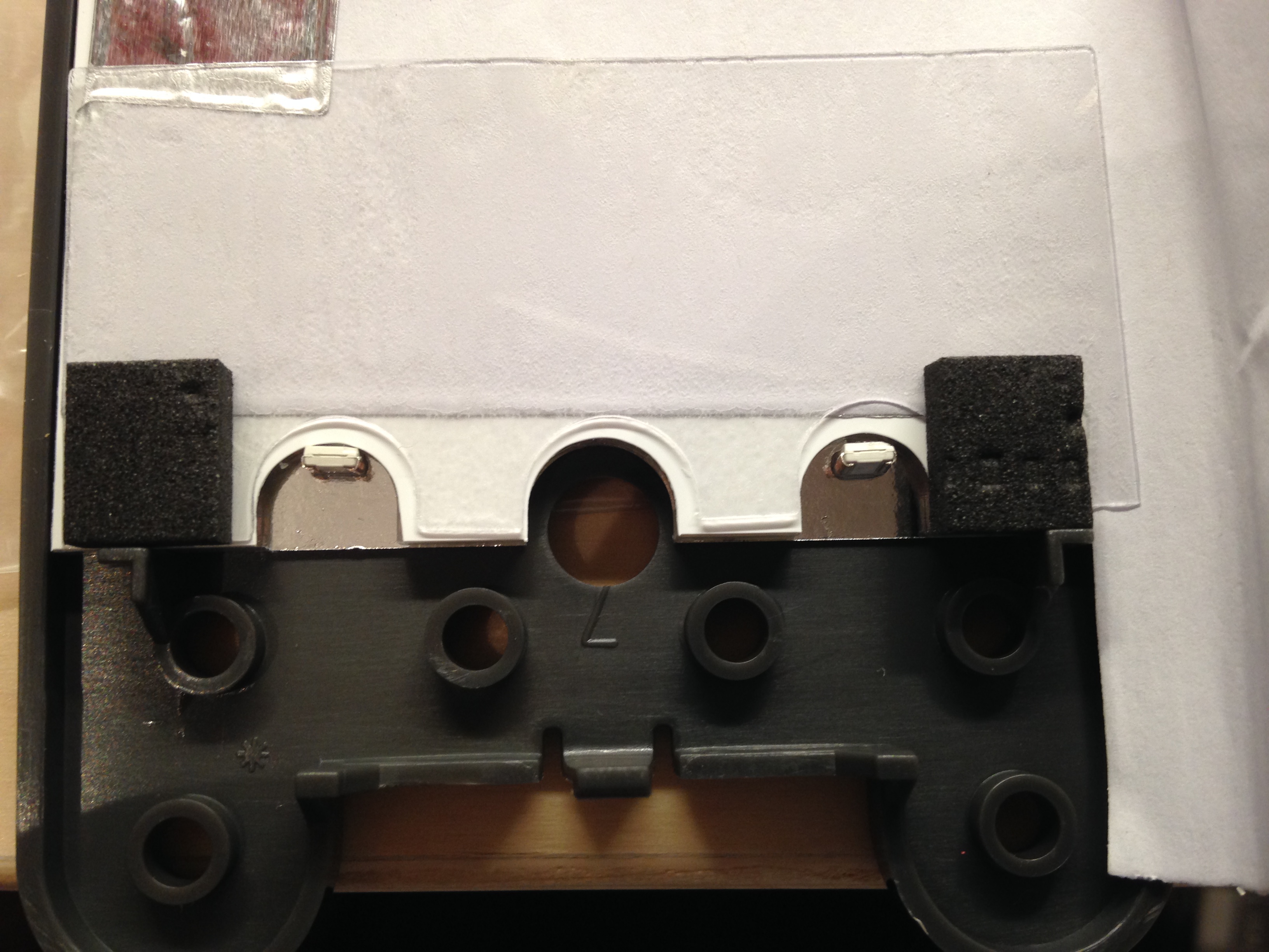
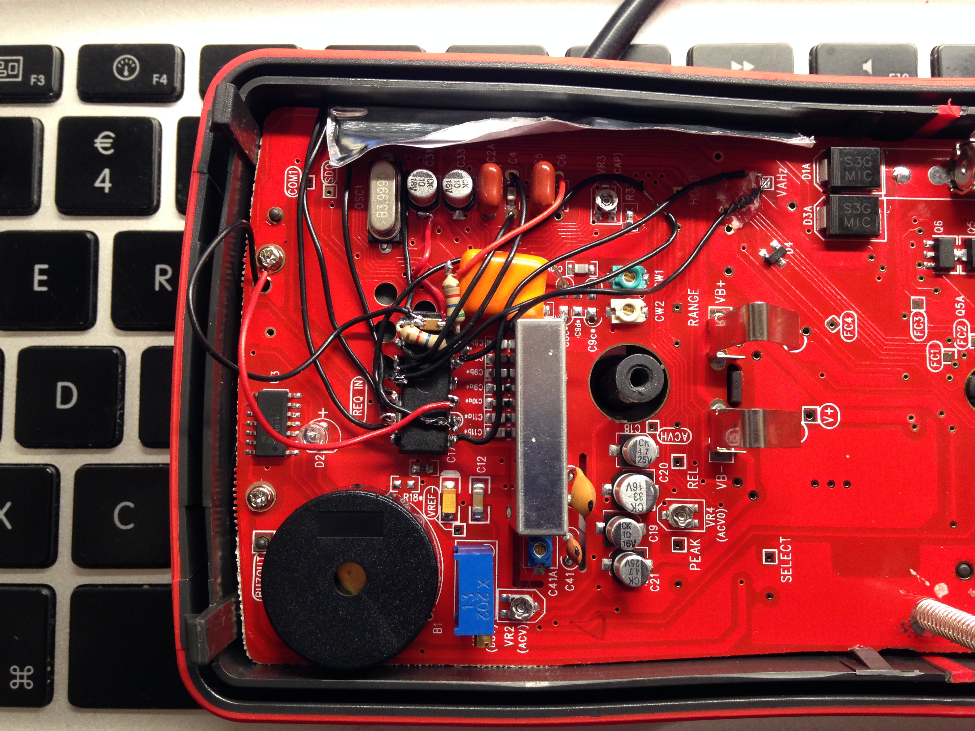
Some pictures;