June 1, 2017

New product in the store: Slot car programmer


The new product is called SSD Slot Car ID programmer. The main purpose is to assign Slot car IDs to Scalextric Sports Digital slot cars. In a typical usage situation the slot cars for the upcoming race can be programmed with the correct car ID already before the ongoing race have finished.


It can be controlled by either pushing the button, or by connecting a computer to the serial interface. The serial interface configuration need to be TTL level and 1N8 19200. Sending any character 1-6, will set the car ID to respectively address.

Here is the manual for more information.

December 2, 2016

Wireless Pulse Counter 3 (WPC3)

I have updated the firmware to support the Telldus products.
For Telldus products it is needed to convert the received data into Energy and Power consumption.
An example how this is done can be seen in the file wpc-calc.c here.

Another update is the 1-wire support. Now the WPC can communicate to the same 1-wire-devices as the WMS mk3.
  • DS18B20
  • DS18S20
  • DS1820
  • DS18B22
  • DS2450
  • MAX31850K
Of course is the DHT22 also supported.

The new Wireless Pulse Counter 3 (WPC3) is available now in the foogadgets store.

May 30, 2016

Soon: Wireless pulse counter (WPC2) to support Tellstick DUO/NET

I am currently working on adding support for Tellstick DUO/NET to the WPC2. The support will be implemented in the same way as the old WPC.
The 1-wire support will at the same time, be extended to be compatible with more devices.
Beta testing is ongoing.

February 5, 2016

New CO2-sensor support for the WMS mk3

I have implemented support for an additional carbon dioxide sensor that is much cheaper and easier to get hold of compared to the S8 sensor from SenseAir.

The new sensor (MH-Z19) can be found on eBay or Aliexpress from $26 including shipment.

Of course there are differences between the two that is reflected by the price.

I have setup two WMS mk3 side by side. One WMS with an S8 sensor and one with an MH-Z19 sensor. The result is logged to ThingSpeak

The MH-Z19 variant used have a range from 0-5000ppm. As the digital output on the MH-Z19 only can be 0-1000, every digital step represents 5ppm. This probably contributes to the jagginess in the graphs presented below.

First observation when comparing the two graphs is that the MH-Z19 sensor gives a much more jagged curve. Both graphs have the same shape which indicates that the response time is about the same for both. The MH-Z19 has however a slower response time.

The left half of the graphs below should be close to 400ppm as both sensors was placed in the opening of a window. Outside air can be used to calibrate a CO2 sensor since the open air CO2 concentration is constantly very close to 400ppm.

A feature that the MH-Z19 is lacking compared to the S8 is auto calibration (a.k.a. ABC - Automatic Baseline Calibration). The ABC continuously keeps the S8 sensor calibrated.

This picture shows the difference between the two. The timescale is 1 hour.
This second image shows that the MH-Z19 averages out to shape the same graph as the S8, but the readout is not very smooth. The graph spans about 1 hour to make the comparison more obvious.

Another image that shows the jagged graph from the MH-Z19 sensor.
In the graphs below I had added a +45ppm offset to the MH-Z19 sensor readings as I thought it was showing around 45ppm too much compared to the S8. After calibration I reconsidered and had to change the offset factor to -30ppm. The offset change can be seen at about 14:50. When zooming out the comparison between the two is more fair.


Summary

The price/performance ratio for the MH-Z19 is good, and I think it is worth its price and good enough to measure the air quality in an apartment or house. The S8 on the other hand seem to be very much more accurate and there is usually no problem to detect presence of one or several persons in my 97m2 apartment.

I will update the blog when the 0-2000ppm MH-Z19 sensor arrives. That variant is likely to give better results as the resolution of the output is 2ppm per step.

Note that the output of the MH-Z19 is always 0-1000 which is shown by the WMS as 0.0°C - 100.0°C
To convert this to a proper carbon dioxide ppm reading, the temperature need to be multiplied by 50.0 for the 0-5000ppm MH-Z19 variant, and by 20.0 for the 0-2000ppm variant.


September 22, 2015

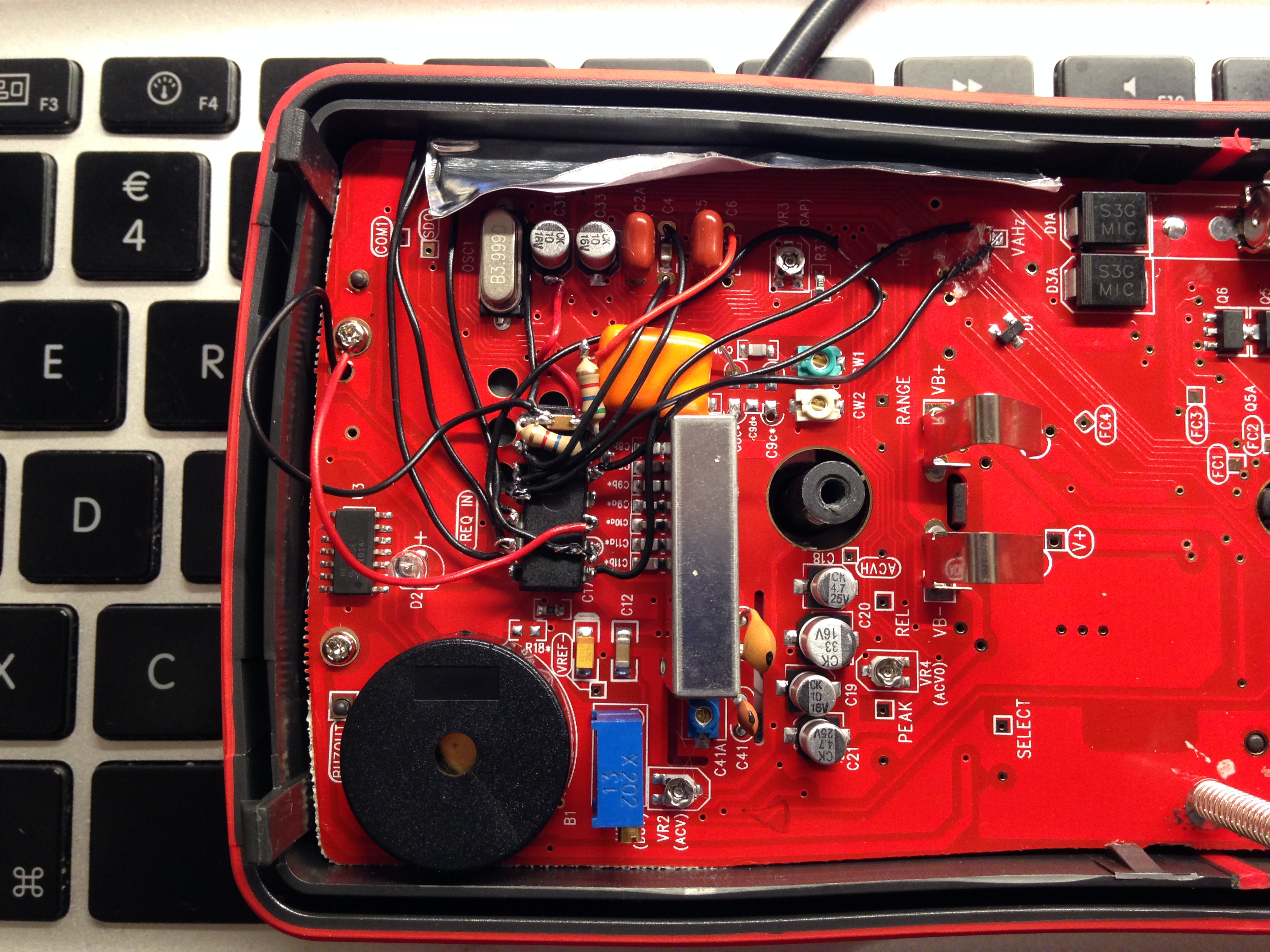
UNI-T UT61E modification

To create my foogadgets I need tools. Some tools can be upgraded and improved.
One of them is my multimeter UT61E from UNI-T that is a pretty good multimeter for the hobbyist.

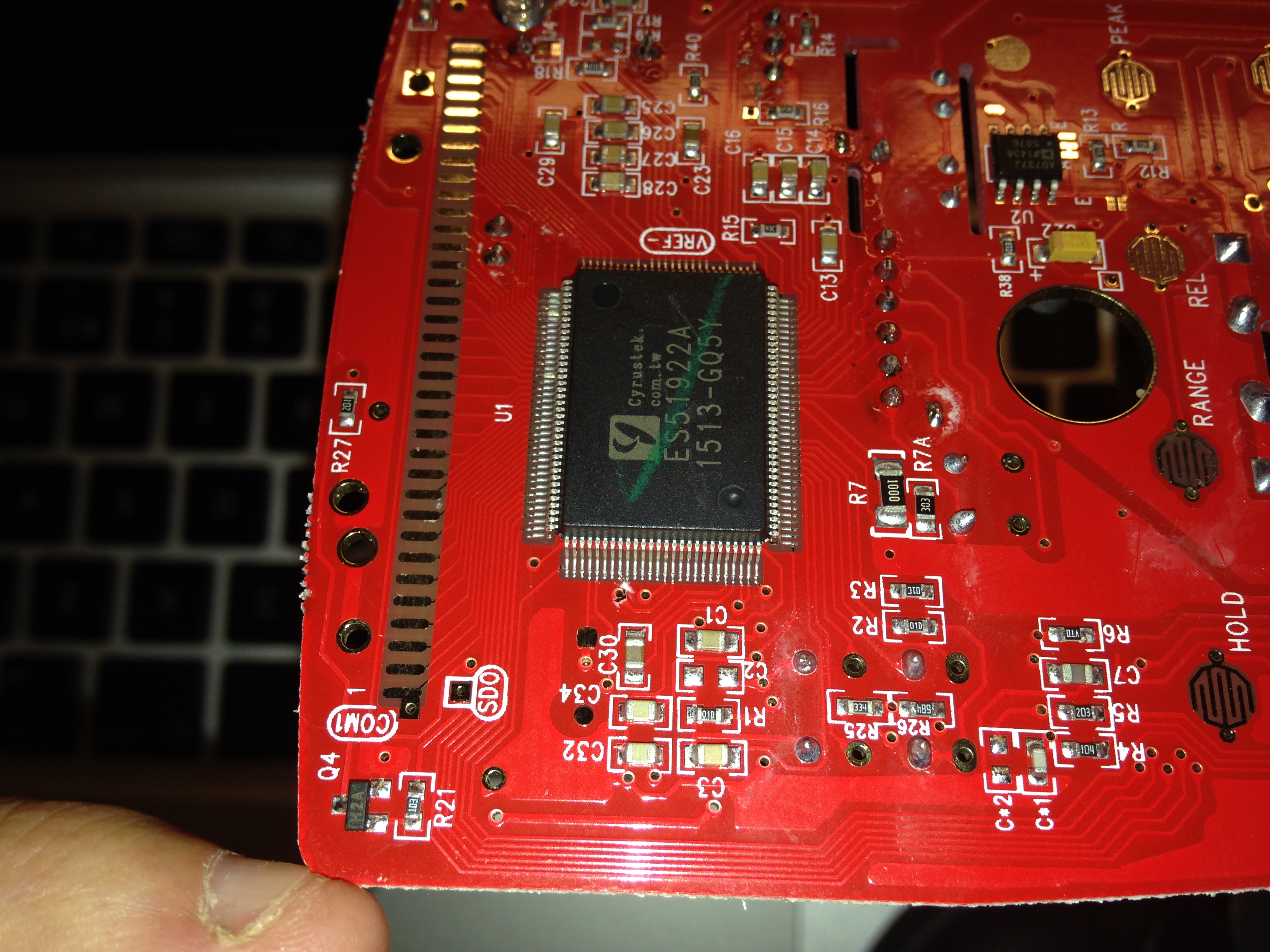
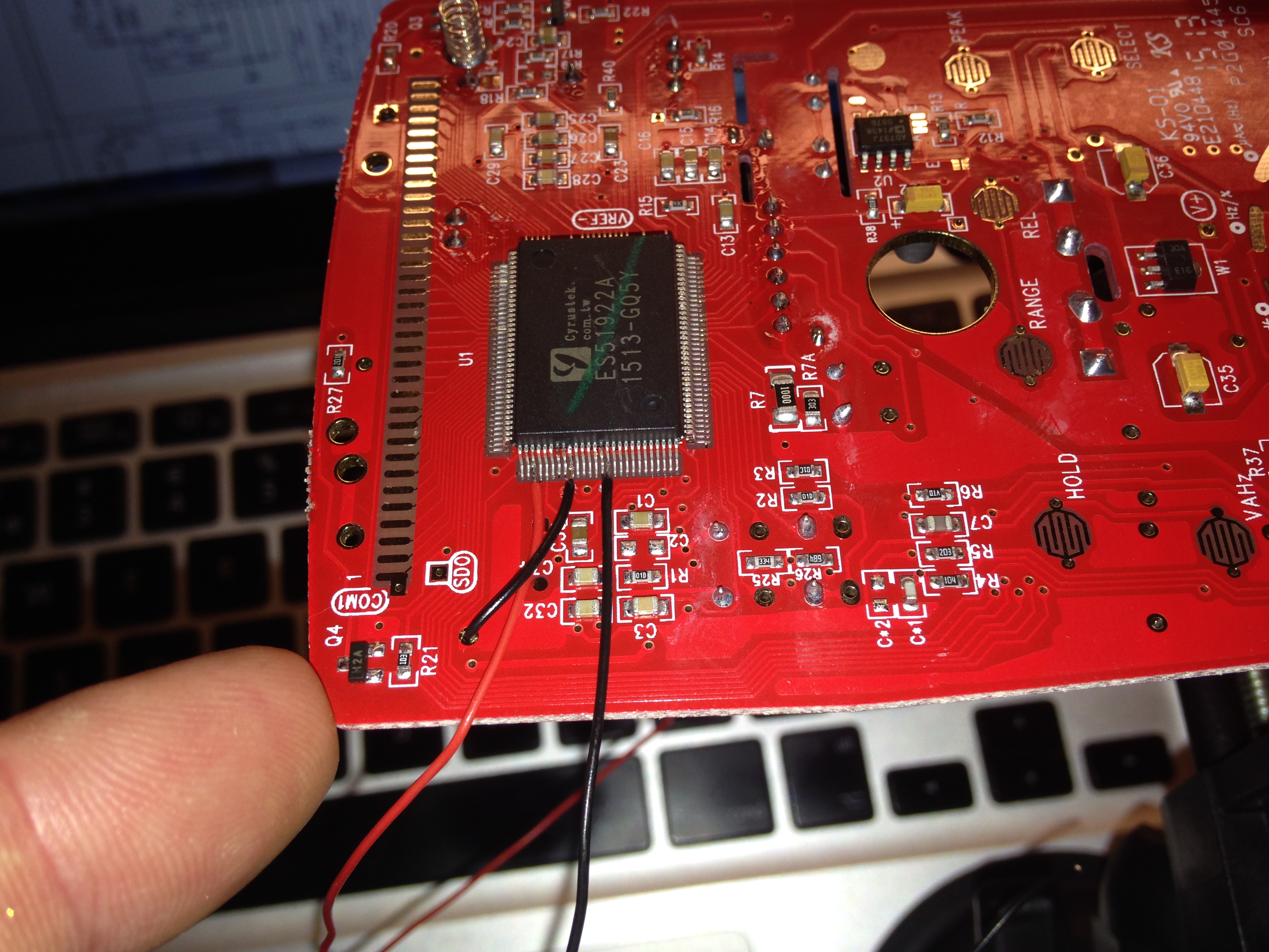
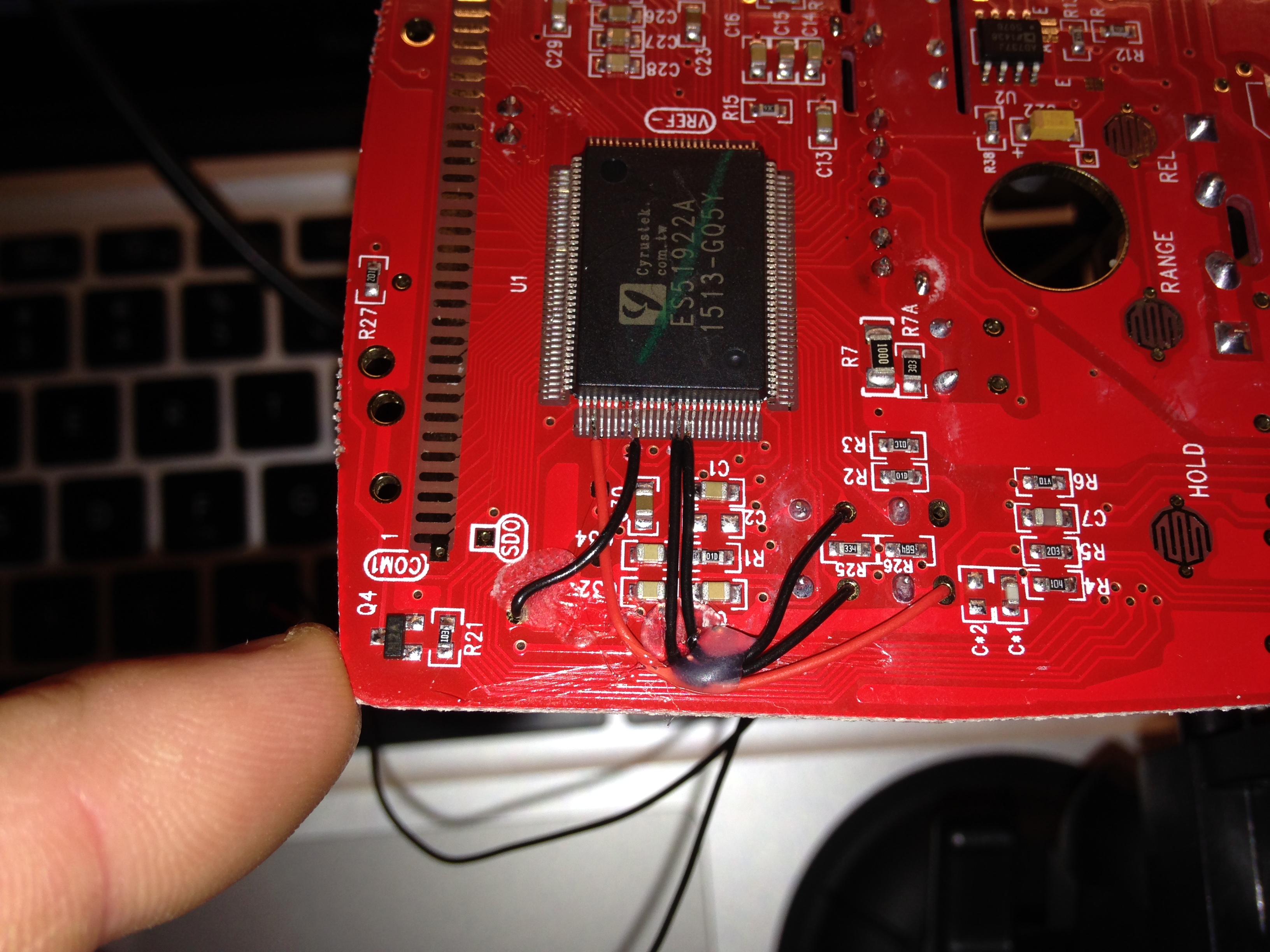
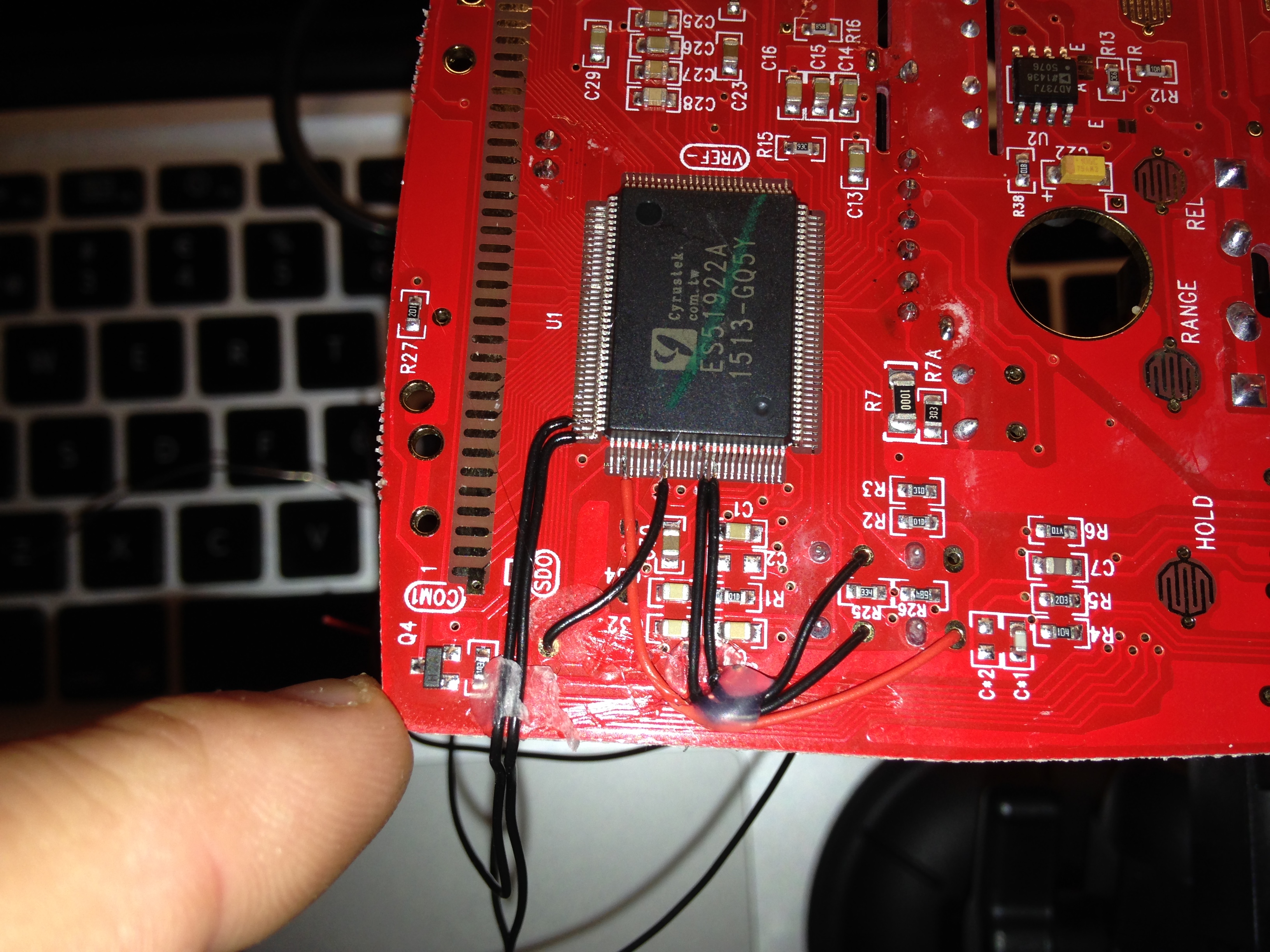
The onboard processing chip ES51922 have more features than is presented to the user. This hack enables some of them.

After the modification my multimeter have the following additional features;
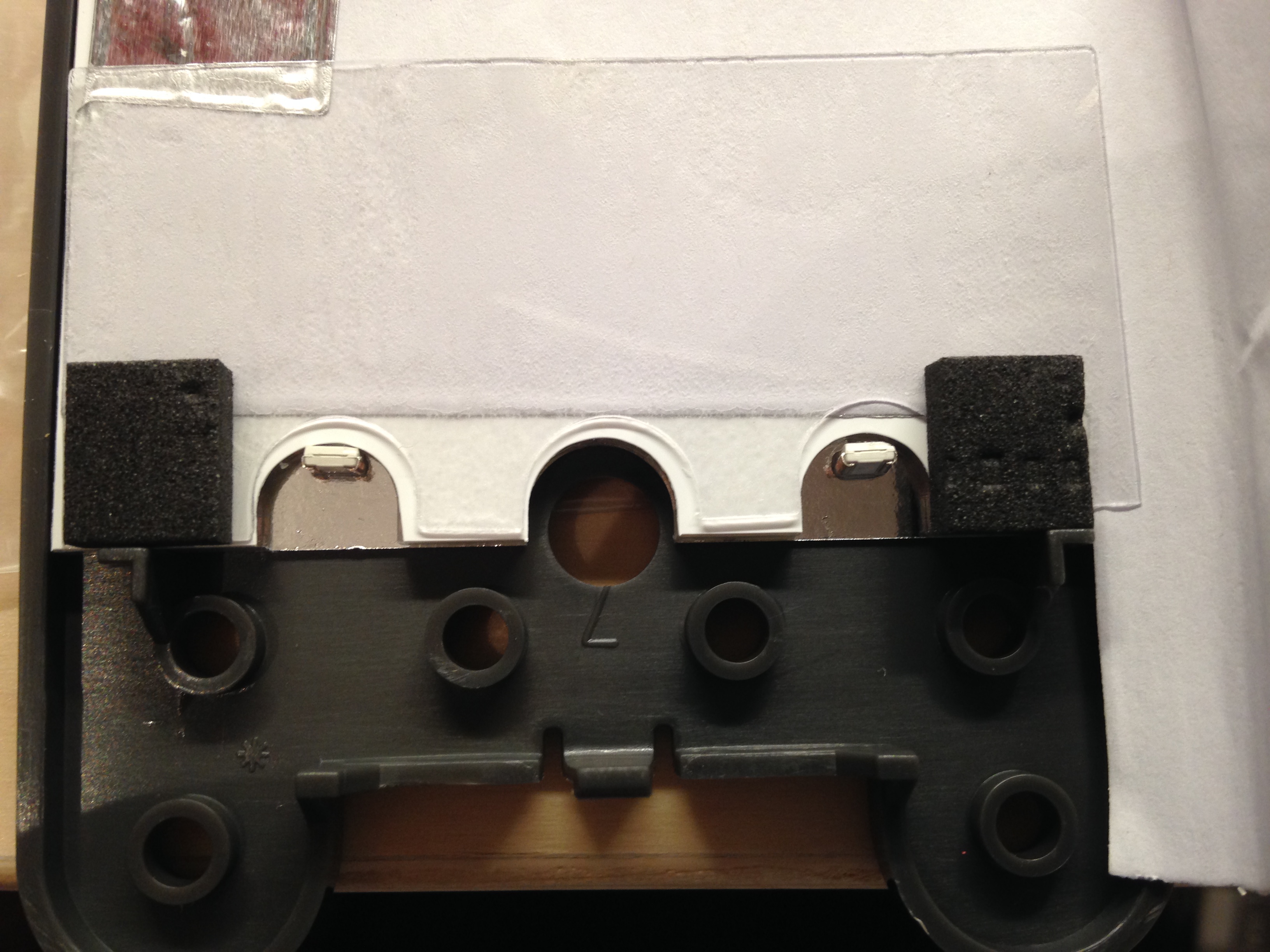
  • Backlit LCD with backlight auto shut-off
  • DMM auto power-off after 15 minutes
  • Possible to Enable/Disable RS232. Default is to have RS232 Disabled
  • MAX-MIN mode for Frequency and Duty cycle measurements
  • AC Low Pass Filter mode
There are some more tweaks to the tweak that can be done;
  • Increase LCD backlight shut-off time from 60 to 180 seconds by connecting BKSEL (113) to VB_ (-3V). It is floating by default
  • Increase the auto power-off time to 30 minutes by connecting APOSEL (112) to VB_. Default is floating.
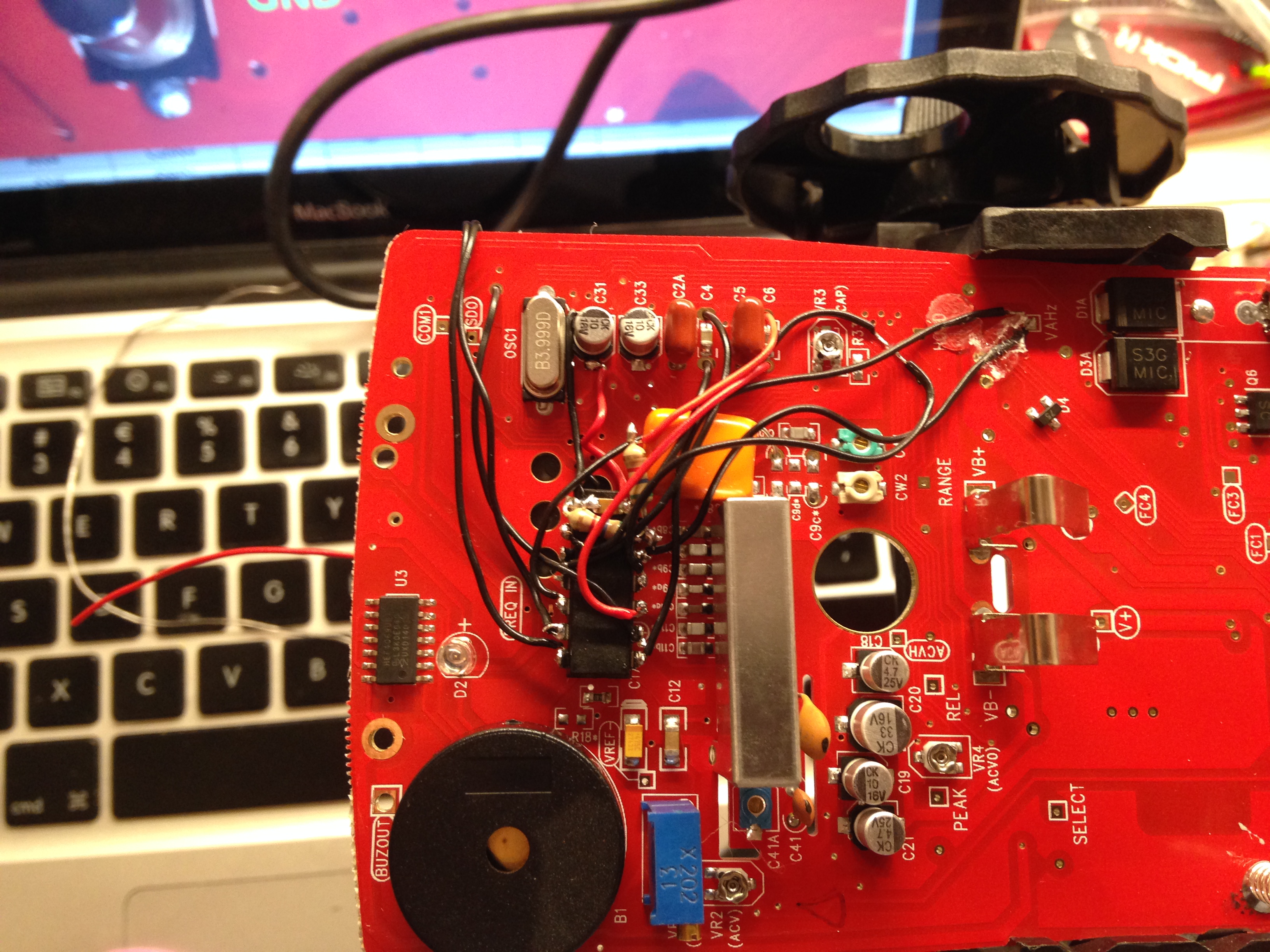
For this modification there is no need to add any extra buttons. By putting a microprocessor between the function buttons and the DMM processing chip, it is possible to add more modes to some of the buttons. For the Blue and the Yellow button there is only one mode, the short press-release.
I add more modes that is triggered by long-pressing each button or by pressing both buttons simultaneously or by holding down the yellow button while powering on.

This is not my own hack but rather a compilation of already existing hacks with some additions.
I have however not seen anyone done this with a PIC from Microchip. Nor using the PIC to drive the LEDs to protect the MM processing chip.
I have also enabled the LPF in AC-mode which I have not seen been done earlier.

Prerequisites

  • 2 pcs LED. The forward current must not exceed 3V
  • 1 pcs Resistor to limit the current to the LEDs. Its value depends on the LEDs forward voltage drop
  • 2 pcs Resistor as a voltage divider for the BKOUT signal. Around 40k-60k should be OK.
  • 1 pcs PIC16F688 microprocessor from Microchip
  • 1 pcs 0.1uF capacitor for decoupling the PIC16F688
  • Thin connection wire
  • Hot glue and super glue is good to have
  • PicKit2 or PicKit3 to program the PIC16F688 microprocessor

The modification

Download the source code from here,
https://bitbucket.org/foogadgets/ut61e-modification

Build the hex-file.

Flash the PIC16F688 with the generated hex-file.

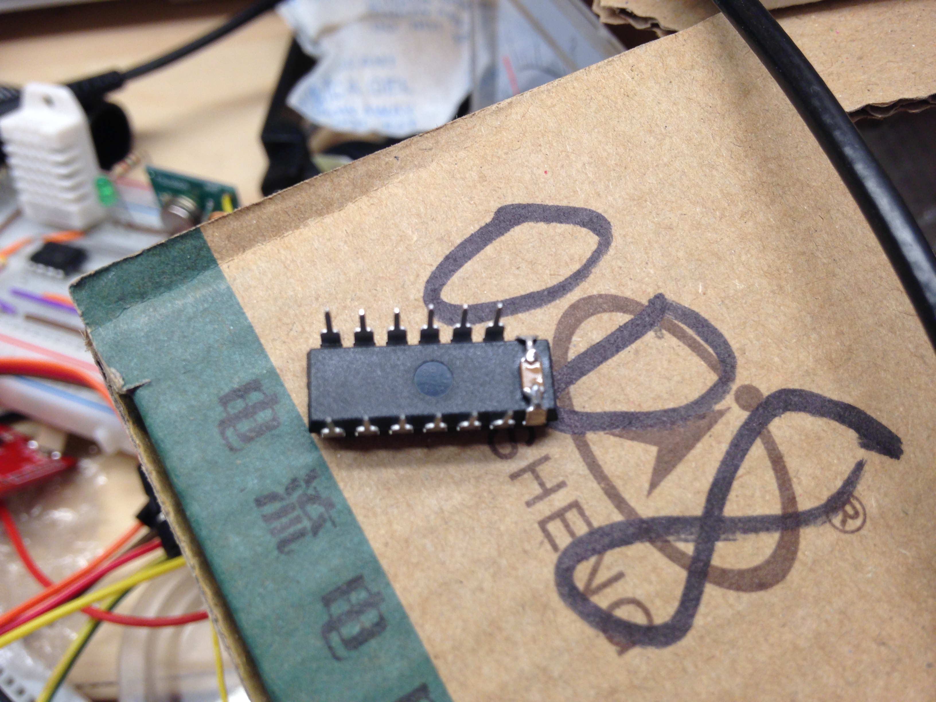
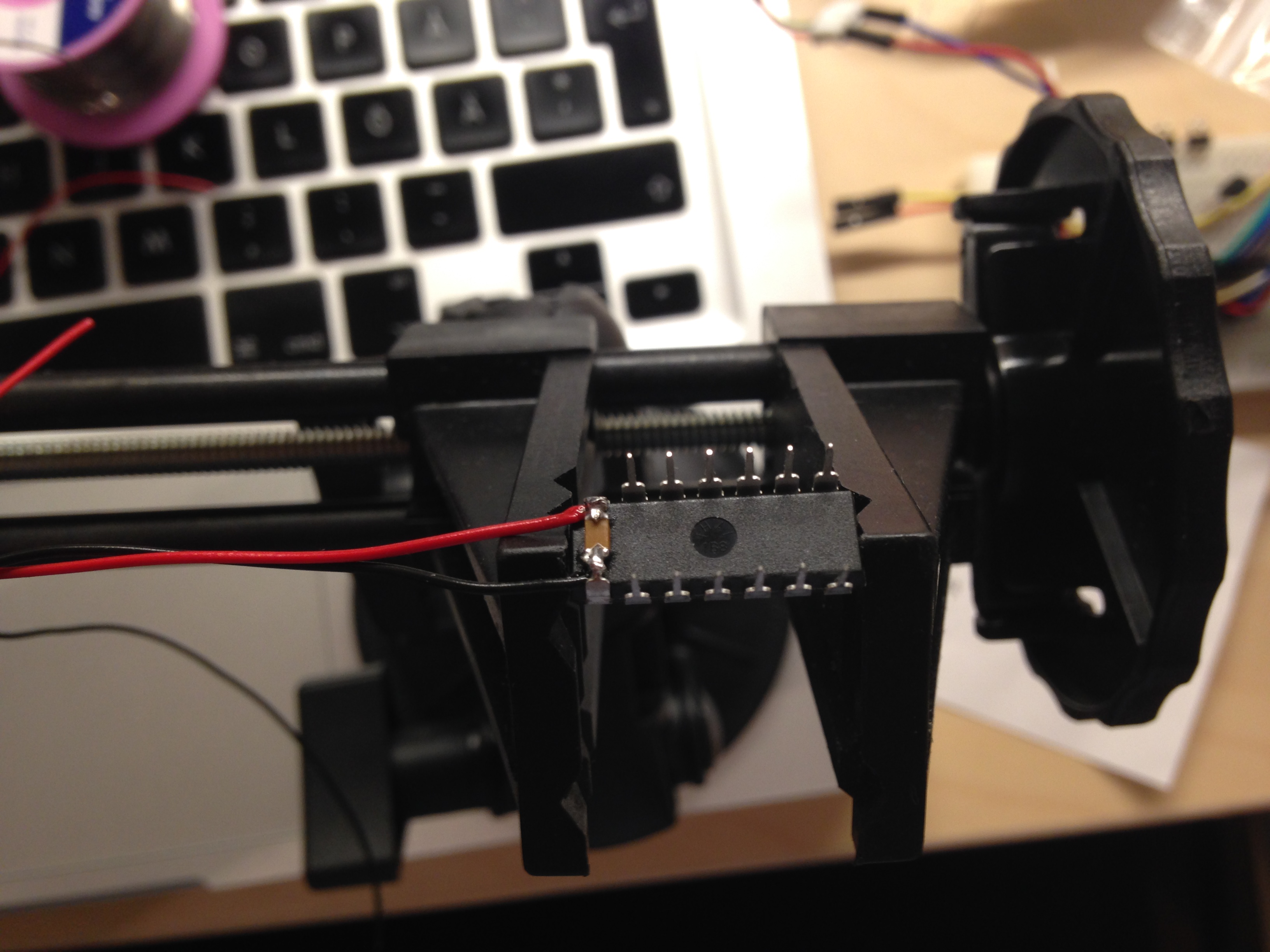
Solder the decoupling capacitor between pin (1) and (14) on the PIC.

Solder thin cables on all pins except pin (4).


Here is a video of the final result,
https://www.youtube.com/watch?v=KLrDdRcWR2Y

Some pictures;


May 3, 2015

How to make the WPC work in Domoticz


Updated 2016-12-04: Updated to reflect Mattias new lua-script.


Here are some short steps to get the WPC working in Domoticz.

1. Enable the X10 protocol.
In Domoticz: Click Setup and then Hardware. Click Set Mode for the RFXtrx433(E). Check the X10 checkbox if not already checked.
The WPC should after this, be shown as a RFXMeter
(In Domoticz you can fully ignore the other type of protocol the WPC transmits. i.e. Temperature/Humidity sensor with ID 4600)

2. Turn on and find the WPC in Domoticz.
In this step, the WPC does not need to be mounted to your electrical meter or Gas meter or whatever you like to count. It just need to be powered on and within range of the RFXtrx433(E)
Click Setup then Devices. Click the button All Devices and locate the RFXMeter sensor in the list. The WPC transmits a signal immediately at power on, and the once every 60 seconds, so it should be found in the list.

3. Add the RFXMeter to your list of Used sensors.
Click the green circle with white arrow pointing to the right, on the right most side of the page.
If it is a blue circle, it is already added to your list of Used sensors.

4. Name your RFXMeter sensor.
Click on the tab Utility in the top. Locate the RFXMeter, and click Edit and give it a name of your choice. This name will be used further down in this list. Also choose Type Energy in the dropdown list (if that is what you like to measure).

5. Add device that show Power consumption [W].
To be able to not only see Energy [Wh] but also see the Power usage [W], please download this excellent lua-script from one of my customers (credit to Mattias Hedström), https://github.com/mrhedstrom/domoticz/blob/master/scripts/lua/script_device_ActualEnergy.lua
To make it work, you need to follow step 5.1 to 5.3 below.

5.1 Create an Electric virtual sensor.
Click Setup and then Hardware. As Type, choose Dummy... Add a name and click Add.
From the newly created Dummy-device, click Create Virtual Sensors. In the drop-down list choose Electric...
Click Setup and then Devices. Click All devices. You should be able to find your newly created Electric virtual sensor. Make note of its idx for later use.

5.2 Modify the script to fit your local settings.
energyCounter: This should be the same string as the name you gave to the RFXMeter in step 4 above.
dummyEnergyMeter: This should be the same string as the name you gave to the Electric Virtual Sensor created in step 5.1
dummyEnergyMeterid: Use the idx integer of the Electric Virtual Sensor created in step 5.1 above.
Now all the software is in place and you should get reports once every minute from the WPC to Domoticz.

5.3 Place the updated script in the Domoticz subfolder <path-to-domoticz>/scripts/lua/

6. Mount your WPC in a secure and light tight fashion onto your Energy meter and enjoy your graphs in Domoticz.


Credit to Mattias Hedström and Patrik Nordelind for helping out making this list.