I have updated the manual with more information and more describing pictures.
The manual can be downloaded here. PDF version here.
February 6, 2015

August 27, 2014
Troubleshooting the Wireless Pulse Counter
In most cases the Wireless Pulse Counter is just plug and play. But if you do have problems getting readings from your Wireless Pulse Counter, please have a look at this trouble shooting guideline.
I will update this post when needed.
The WPC show up in TelldusCenter (or similar), but the counter value is not changing:
I will update this post when needed.
First. Make sure your Tellstick DUO/NET have a firmware equal to, or higher than 12 for DUO or 17 for NET or 79 for RFXtrx433. Here is more information for the Tellsticks, http://developer.telldus.com/blog/2014/04/03/tellduscenter_2.1.2. In this firmware version there has been a correction in the Fineoffset protocol that enables the checksum feature in the protocol. This will ensure that you do not get any false readings.
The WPC does not show up in TelldusCenter (or similar):
- Make sure that the LED on the WPC is blinking once every minute. The LED blink when it transmit data. Even if it has not detected any blinks.
- Make sure that the Tellstick blinks at the same time the WPC LED blink. This indicates that the Tellstick have received and decoded the data.
The WPC show up in TelldusCenter (or similar), but the counter value is not changing:
- Make sure that the "eye" of the WPC can receive pulses. Aim a standard TV-remote to the "eye" and press a button. Make sure that you do this where there is very dim light. The next transmission you get should then be seen as an increased value.
- If the LED blinks more often than once every minute. If it blinks every 10 seconds or so. Then it is likely that you use a USB power pack that is too "smart" for the WPC. Some of the power packs automatically shut down if there is no load. The WPC draws so little power that some of the power packs thinks that nothing is connected and turns off and on. When it restarts all the time, it will always send the same value.
The WPC show up in TelldusCenter (or similar), but the counter value is unreasonably high:
- It is likely that there are false detections. This could be due to light coming in from the sides of the WPC and the Electric meter. Use for example styrofoam to make a tight mounting. Cut out a sheet and make a small hole for the WPC "eye" (the phototransistor) and place it all right on top of the LED on the Electric meter.
August 20, 2014
WMS Mk2 - Currently supported devices
Here is a list of currently supported devices (WMS Mk2 sold after August 1st, 2014).
http://foogadgets.tictail.com
EDIT (2014-09-15): I have removed the support for DS276X since the configuration of the chip and also the extra calculations needed to present a valid sensor reading, was too complex.
To read Thermocouples I recommend the MAX31850 instead.
1-wire networks could be big as long as they are well built. The WMS Mk2 has successfully been tested in a network with 33 sensors and 75m length.

http://foogadgets.tictail.com
EDIT (2014-09-15): I have removed the support for DS276X since the configuration of the chip and also the extra calculations needed to present a valid sensor reading, was too complex.
To read Thermocouples I recommend the MAX31850 instead.
- AM2302 - Temperature and Humidity sensor in one capsule.
- DHT22 - Temperature and Humidity sensor in one capsule.
- All kinds of passive switches with an ON/OFF function. Some examples,
- Tilt switch
- Vibration switch
- Doorswitch
- Float switch
- All kinds of sensors that output 0-5V digital signal. Some examples,
- CO2 sensor (S8 from SenseAir)
- 1-wire products from Maxim Integrated,
- DS18B20 - Digital thermometer
- DS18S20 - Digital thermometer
- DS1820 - Digital thermometer
- DS1822 - Digital thermometer
- DS1825 - Digital thermometer
- DS2450 - 4 channel A/D converter
DS2760 - High-precision Li+ battery monitorDS2761 - High-precision Li+ battery monitorDS2762 - High-precision Li+ battery monitor- MAX31820 - Ambient temperaure sensor
- MAX31826 - Digital temperature sensor
- MAX31850K - Cold-junction compensated thermocouple Type K
- MAX31851 - Cold-junction compensated thermocouple Type S and R
- ... or any other sensor/device based on any of the 1-wire products above
- https://www.m.nu/adomvandlare-4-kanaler-025v-dc-p-307.html
- https://www.m.nu/adomvandlare-4-kanaler-05v-dc-p-455.html
- https://www.m.nu/barometer-version-2-p-439.html
- https://www.m.nu/co2matare-version-2-p-259.html
https://www.m.nu/fuktmatare-p-340.html- https://www.m.nu/ljussensor-analog-version-12-p-186.html
- https://www.m.nu/temperatursensor-for-tuffa-miljoer-ds18b20-p-252.html
- https://www.m.nu/temperatursensor-med-metallfilm-ds18b20-p-269.html
- https://www.m.nu/temperatursensor-pa-kabel-ds18b20-p-44.html
- https://www.m.nu/temperatursensor-pa-kretskorti-plastbox-p-456.html
https://www.m.nu/termoelementinterface-mat-hoga-temperaturer-version-2-p-457.html- https://www.m.nu/thermocouple-amplifier-with-1wire-breakout-board-max31850k-p-1392.html (remember to also order the level shifting board)
1-wire networks could be big as long as they are well built. The WMS Mk2 has successfully been tested in a network with 33 sensors and 75m length.
August 13, 2014
New Firmware and Manual for the WMS Mk2
Just before the summer vacations I finalized the Wireless Multi-sensor Mk2 firmware that I have been working with for quite some time.
News,
Improvements,
News,
- CO2 sensor S8 from SenseAir is now supported. It can be connected to the Event Input after changing the input mode of the Event Input (c.f. Manual). You can get the CO2-sensor here.
- MAX31850K support. This chip is a Thermocouple Type K to 1-wire chip. This makes it possible to make a Type K thermocouple wireless. It can output 409.6°C as the highest temperature. It is a limitation set by the protocol I use. Here you can find a MAX31850K-module, m.nu.
- DS2450 support. This is a 4 channel AD converter. All 1-wire sensors based on this chip will be compatible with the WMS Mk2. This, this, this, this and this is also compatible modules since they are based on the DS2450 chip.
Improvements,
- Events are now sent as a LMST-606 device. An ON or OFF signal will be sent depending on if the input pin is pulled up or pulled down.
- The Manual is out in a first revision.
All Wireless Multi-sensors Mk2 will be shipped with this new firmware from now on.
May 13, 2014
The Wireless Pulse Counter will take over from the old Wireless Energy Meter
EDIT (2014-09-21): I have added RFXMeter compatibility so that the WPC will show up as a RFXMeter and thus be natively supported in Domoticz. Available in WPC sold from this date. Here is an instruction for how you configure it in Domoticz.
EDIT (2014-09-15): Added information about support for the LED-pulse detector from m.nu.
The old Wireless Energy meter serves its purpose, but it has a few shortcomings.
Here is a new product that I call Wireless Pulse Counter (WPC). This is a better name compared to the old Wireless Energy Meter, since it is actually only counting pulses, not energy or liters.

Since it is only counting pulses it is also much more versatile.
From the counted pulses you can then calculate the consumed water/energy/gas/events etc.
The new WPC will fit perfectly in a plastic box from Hammond, with the dimensions 20x35x50mm. Note! I have not decided on a box with or without flanges as in the pdf.

The power feed is changed to a micro-USB instead of a mini-USB connector. In this way you will very likely already have a power source for it. You can just reuse an old Android-mobile charger to power it.
Most people do not have a soldering station at home. This version comes with screw terminals so that a soldering station will never be needed.
It is professionally assembled with perfectly soldered components.
Further more, I have changed the protocol to a simpler variant. All credits to Stefan Strömberg at OpenNetHome for this suggestion.
With this new protocol you can drop several packages. Lots of packages. Still, even with only a few packages received, you can trust that they reflect the consumed energy. The solution is utilise the Humidity data field as counter data in the same way as with the temperature data field. In this way it is possible to have an always increasing counter.
It will wrap around, but the maximum counter value will be so big so that there will need to pass several hours of lost packages to mess up the energy logging.
Note that in the normal case you do not loose many packages, so the above text describes the extreme situation.
As soon as I have finished the verification of the hardware, I will make it available in the foogadgets store.
EDIT: It is now available in the web-store foogadgets.tictail.com.
EDIT (2014-09-15): Added information about support for the LED-pulse detector from m.nu.
The old Wireless Energy meter serves its purpose, but it has a few shortcomings.
Here is a new product that I call Wireless Pulse Counter (WPC). This is a better name compared to the old Wireless Energy Meter, since it is actually only counting pulses, not energy or liters.
Since it is only counting pulses it is also much more versatile.
- You can combine the WPC with a reflex detector (TCRT5000) and measure water flow, gas consumption or electric energy consumption if it is of the rotating disk type.
- You can count the amount of blinks from an Electric energy meter. Both LED and S0 output is supported.
.png) | |
|
- You can also connect the LED-pulse detector from m.nu.
%2B(1).png) |
| The LED-pulse detector from m.nu is very very sensitive. The sensitivity can be reduced by adding a resistor R between S0- and GND on the WPC. A value between 820Ω and 4k7Ω seem to be reasonable values. Lower value => lower sensitivity. |
From the counted pulses you can then calculate the consumed water/energy/gas/events etc.
The new WPC will fit perfectly in a plastic box from Hammond, with the dimensions 20x35x50mm. Note! I have not decided on a box with or without flanges as in the pdf.
The power feed is changed to a micro-USB instead of a mini-USB connector. In this way you will very likely already have a power source for it. You can just reuse an old Android-mobile charger to power it.
Most people do not have a soldering station at home. This version comes with screw terminals so that a soldering station will never be needed.
It is professionally assembled with perfectly soldered components.
Further more, I have changed the protocol to a simpler variant. All credits to Stefan Strömberg at OpenNetHome for this suggestion.
With this new protocol you can drop several packages. Lots of packages. Still, even with only a few packages received, you can trust that they reflect the consumed energy. The solution is utilise the Humidity data field as counter data in the same way as with the temperature data field. In this way it is possible to have an always increasing counter.
It will wrap around, but the maximum counter value will be so big so that there will need to pass several hours of lost packages to mess up the energy logging.
Note that in the normal case you do not loose many packages, so the above text describes the extreme situation.
EDIT: It is now available in the web-store foogadgets.tictail.com.
March 20, 2014
Assembly instruction for the Wireless Multi-sensor KIT
If you have decided to buy the KIT, you will have some SMD soldering in front of you.
It is not very hard to solder, but if you have a steady hand, a magnifier glass and strong light, it is of great help.
This is the first project for me where I use SMD-components, and with the size of the SMD components that I use, it is actually as fast or faster to solder compared to the old fashion through hole soldering.
Here is an excellent SMD soldering tutorial from the user lizerdboy79 at Youtube, https://www.youtube.com/watch?v=PxeWVCS15RU
When you receive your kit you first need to make sure all components are there.
Things you will need is,
Good to have,
You start to solder the components that build the lowest height from the PCB. That is the resistors, capacitor and LED. The orientation of the resistors and capacitor is not important. The resistors however must have the black side up.
The LED must be soldered with the right orientation. The bottom side of the LED has an arrow. This arrow should point to the (-)-marking on the PCB where the LED should be soldered.
Start with cleaning the soldering pads on the PCB where the components will go. Then put some solder on one of the soldering pads for each component.
Take one component with the Tweezers and place it on the PCB. Pre-heat the pad where you put the soldering tin, and push in the component into the melted tin. Be quick. Remove the soldering tip. Let cool, and release the tweezers.
Once this is done, you can go ahead and solder the other side of the component.
Repeat for the rest of the SMD resistors, capacitor and LED component.
R1 - 1k
R2, R3 - 4k7
R4 - 4k7 (This resistor is optional. In the kit I have provided a 3-pin-header and a jumper instead)
Next is the mini USB type B connector (If you will use it).
 The red arrows marks the power-pins. The yellow marks the data-pins.
You must solder the power-pins. Some USB power supplies automatically shut down if they do not sense any load between the data-pins (D+ and D-). This can be overcome by putting a solder blob between pin 2 and 3.
Add some flux to all the soldering pads.
Put some solder on one of the chassi pads.
Press the connector in place and apply heat to the soldering pad where you added the tin.
You should notice that the component sinks into place.
Solder the rest of the 3 chassi pads.
Last you solder pin 1 and pin 5 of the usb connector. They represent Vcc and GND.
If you want you can put a tin blob shortening pin 2 and 3. This will make sure that you can use any USB-charger to power the Wireless Multi-sensor.
Next up is the DIP 8 IC socket for the PIC12F675 microcontroller.

The orientation of the socket is not as important as the PIC12F675 orientation. However, there is a marking in the PCB that corresponds to the marking in the DIP-socket. Orient it accordingly. The red ring marks where pin 1 on the PIC12F675 goes.
Add some flux.
Place the DIP-socket in place and turn the PCB upside down.
Solder two of the pins in opposite corners. Pin 1 and 5 for instance.
Pick up the PCB and apply pressure on the DIP-socket and heat the pins where you soldered one at the time.
You should feel the socket sinks into place.
Solder the rest of the pins.
Place the PIC12F675 into the DIP-socket oriented as in the picture below.
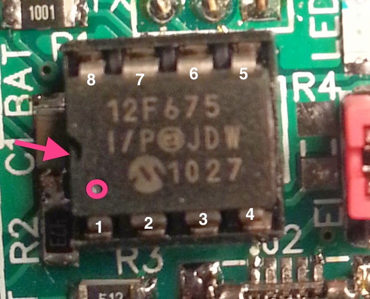
The last thing to solder is the 3-pin header in the EI position (EI = Event Input).
Put the pin header in place and turn the PCB on the back and solder one pin.
At this point the pin header is probably not very straight positioned. Pick the PCB up and put one of your fingers on top of the pin header while you heat the pin you just soldered.
Make the pin header straight and let cool. Lay the PCB down again on the back, and solder the remaining pins. Once you have soldered all pins you can install the mini jumper, shortening the two pins closest to the LED. This makes sure that the Input pin is pulled to ground when it is not in use. If you forget this jumper and leave the pin header open, you will get sporadic PIR-events.
Continue read about how you mount the additional sensors in another blogpost.
It is not very hard to solder, but if you have a steady hand, a magnifier glass and strong light, it is of great help.
This is the first project for me where I use SMD-components, and with the size of the SMD components that I use, it is actually as fast or faster to solder compared to the old fashion through hole soldering.
Here is an excellent SMD soldering tutorial from the user lizerdboy79 at Youtube, https://www.youtube.com/watch?v=PxeWVCS15RU
When you receive your kit you first need to make sure all components are there.
Things you will need is,
- Soldering station
- Solder tin
- Flux
- Side cutter
Good to have,
- Tweezers (to place components)
- Magnifier
- Strong light
You start to solder the components that build the lowest height from the PCB. That is the resistors, capacitor and LED. The orientation of the resistors and capacitor is not important. The resistors however must have the black side up.
The LED must be soldered with the right orientation. The bottom side of the LED has an arrow. This arrow should point to the (-)-marking on the PCB where the LED should be soldered.
 |
| Bottom side of the SMD LED |
 |
| Marking on the PCB is the Cathode. The LED also has a green spot on the top that marks the location of the Cathode. |
Start with cleaning the soldering pads on the PCB where the components will go. Then put some solder on one of the soldering pads for each component.
Take one component with the Tweezers and place it on the PCB. Pre-heat the pad where you put the soldering tin, and push in the component into the melted tin. Be quick. Remove the soldering tip. Let cool, and release the tweezers.
Once this is done, you can go ahead and solder the other side of the component.
Repeat for the rest of the SMD resistors, capacitor and LED component.
R1 - 1k
R2, R3 - 4k7
R4 - 4k7 (This resistor is optional. In the kit I have provided a 3-pin-header and a jumper instead)
Next is the mini USB type B connector (If you will use it).
You must solder the power-pins. Some USB power supplies automatically shut down if they do not sense any load between the data-pins (D+ and D-). This can be overcome by putting a solder blob between pin 2 and 3.
Add some flux to all the soldering pads.
Put some solder on one of the chassi pads.
Press the connector in place and apply heat to the soldering pad where you added the tin.
You should notice that the component sinks into place.
Solder the rest of the 3 chassi pads.
Last you solder pin 1 and pin 5 of the usb connector. They represent Vcc and GND.
If you want you can put a tin blob shortening pin 2 and 3. This will make sure that you can use any USB-charger to power the Wireless Multi-sensor.
Next up is the DIP 8 IC socket for the PIC12F675 microcontroller.
The orientation of the socket is not as important as the PIC12F675 orientation. However, there is a marking in the PCB that corresponds to the marking in the DIP-socket. Orient it accordingly. The red ring marks where pin 1 on the PIC12F675 goes.
Add some flux.
Place the DIP-socket in place and turn the PCB upside down.
Solder two of the pins in opposite corners. Pin 1 and 5 for instance.
Pick up the PCB and apply pressure on the DIP-socket and heat the pins where you soldered one at the time.
You should feel the socket sinks into place.
Solder the rest of the pins.
Place the PIC12F675 into the DIP-socket oriented as in the picture below.
The last thing to solder is the 3-pin header in the EI position (EI = Event Input).
Put the pin header in place and turn the PCB on the back and solder one pin.
At this point the pin header is probably not very straight positioned. Pick the PCB up and put one of your fingers on top of the pin header while you heat the pin you just soldered.
Make the pin header straight and let cool. Lay the PCB down again on the back, and solder the remaining pins. Once you have soldered all pins you can install the mini jumper, shortening the two pins closest to the LED. This makes sure that the Input pin is pulled to ground when it is not in use. If you forget this jumper and leave the pin header open, you will get sporadic PIR-events.
Continue read about how you mount the additional sensors in another blogpost.
March 19, 2014
Connection guide for the Wireless Multi-sensor
Here are the different connections to the Wireless Multi-sensor version 1.1.
First I start with presenting the different ways to connect sensors,
In the end I show how you can power the Multi-sensor and where you can feed it, under the section Power.
 The 1-wire network is ideally a straight bus. But it could as well be pure star-shaped. This shape is however not recommended by Maxim. For more detailed information about the network topology I recommend reading Guidelines for Reliable Long Line 1-Wire Networks.
With the DS2423-firmware the Multi-sensor will support the DS2423-2-channel counter commonly used when logging energy consumption. however there is a simpler way.
The DHT22 can be connected with up to 100m cable according to the specification.
 You can choose from many different types of sensors to connect to the PIR-input. Any of those types (or similar) can be connected right into the pin connector after removing the read jumper thing.
 Any passive switch-type of sensor can be connected to the PIR-input. With this type of sensor you will need to add a Pull-down resistor to force the DATA-line low when the switch is open. The pull-down resistor should have a value of about 4k7 to 10kOhm, but it is not critical.
A transmission will only be done as soon as the DATA-line goes high.
You will be safe to feed the Multi-sensor with 4.5-5.5V independently of which sensors you combine. The easiest way is to use a USB-charger or similar. The USB port is only there to give power to the Multi-sensor. The D+ and D- pins are not used.
If you want to minimise the form factor you will likely want to choose a small battery. It can be useful to know that you can go as low as 3.0V as long as you only use 1-wire DS18X20 sensors. I have successfully powered a Multi-sensor and one DS18B20 with a CR2032 cell battery (3V). The test was speed up with increased transmission interval. The estimated lifetime of this configuration is estimated to more than 1.5 years.
The transmitting range of the Multi-sensor will depend on the voltage level.
Here is the specification for the Radio module used in the Multi-sensor (FS1000A):
For the advanced user it could probably be possible to boost the transmission range by feeding the RF module with 12V separate from the rest of the Multi-sensor.
First I start with presenting the different ways to connect sensors,
- Temperature and Temperature/Humidity sensors
- PIR and CO2 sensors
- Passive switch-type of sensors
In the end I show how you can power the Multi-sensor and where you can feed it, under the section Power.
Temperature and Temperature/Humidity sensors
A network length of about 50 meters have been reported to work OK with the Multi-sensor, but do not see this as the maximum limit. Maximum network length is still to be found. Cable type is important if you plan to build a large network. Pair-twisted EKKX 2x2x0,5 is one of the recommended cables to successfully build a large working 1-wire network.
The following 1-wire sensors have been verified to work, DS18B20, DS18S20, DS18B22, DS1820 and MAX31820.
The following 1-wire sensors have been verified to work, DS18B20, DS18S20, DS18B22, DS1820 and MAX31820.
With the DS2423-firmware the Multi-sensor will support the DS2423-2-channel counter commonly used when logging energy consumption. however there is a simpler way.
The DHT22 can be connected with up to 100m cable according to the specification.
PIR or CO2 sensor
Passive switch-type of sensors
A transmission will only be done as soon as the DATA-line goes high.
Power
You can power the Multi-sensor in one of two ways. Either you use the USB-port, or you use the solder pads on the PCB marked BAT for battery, to power it with the power source of your choice.
The table below will guide you with what minimum and maximum voltages that are allowed.
 |
| The numbers within the parenthesis are the maximum ratings for each sensor. However, the PIC-microprocessor limits the maximum voltage to 5.5V. I have tested it successfully with 6.5V, but that is outside the PIC12F675 specification and not recommended. |
You will be safe to feed the Multi-sensor with 4.5-5.5V independently of which sensors you combine. The easiest way is to use a USB-charger or similar. The USB port is only there to give power to the Multi-sensor. The D+ and D- pins are not used.
If you want to minimise the form factor you will likely want to choose a small battery. It can be useful to know that you can go as low as 3.0V as long as you only use 1-wire DS18X20 sensors. I have successfully powered a Multi-sensor and one DS18B20 with a CR2032 cell battery (3V). The test was speed up with increased transmission interval. The estimated lifetime of this configuration is estimated to more than 1.5 years.
The transmitting range of the Multi-sensor will depend on the voltage level.
Here is the specification for the Radio module used in the Multi-sensor (FS1000A):
| Operating Voltage | 2.5 V to 12 V |
| Operating Current | 4mA @ 5V, 15mA @ 9V |
| Quiescent Current | 10uA |
| Operating Temperature | -10C - 60C |
| Modulation | ASK |
| Max. Data Rate | 2.4K |
| Data Input | TTL |
| RF Power | 20 mW@5V |
For the advanced user it could probably be possible to boost the transmission range by feeding the RF module with 12V separate from the rest of the Multi-sensor.
Subscribe to:
Posts (Atom)